Boiler start up and operations – A.O. Smith 3400 User Manual
Page 41
41
BOILER START UP AND OPERATIONS
IMPORTANT
Only an A. O. Smith Certified Start-up agent must perform the
initial firing of the boiler. At this time the user should not hesitate
to ask the start-up agent any questions regarding the operation
and maintenance of the unit. If you still have questions, please
contact the factory or your local A. O. Smith representative.
Contact Technical Support noted on the back cover for the name
of your closest Certified Start-Up agent.
Lighting and Operating instructions are included with this manual.
By using these instructions, the user may be able to make minor
operational adjustments and save unnecessary service calls.
However the user should not attempt repairs, but should contact
a qualified service technician or gas supplier.
GENERAL
Never operate the boiler without first making sure the boiler and
system are filled with water, in addition:
• Make sure a temperature and pressure relief valve
is installed in the storage tank for hot water supply
installations.
• Make sure that the boiler and system have been purged
of air and checked for leaks.
Also ensure to check the gas piping for leaks before beginning
the initial firing of the boiler.
FILLING AND PURGING OF HEATING BOILER
INSTALLATION
1. Fast fill system through bypass until pressure approaches
desired system pressure. Close bypass valve and permit
pressure to be established by the pressure reducing valve.
2. Vent all high points in system to purge system of air.
Provisions should be made to permit manual venting of radiators
or convectors.
PURGING GAS LINE
Gas line purging is required with new piping or systems in which
air has entered.
INLET GAS PRESSURE
The inlet gas pressure is measured by removing the 1/8” NPT Plug
located on the upstream side of the supply gas control valve, and
insert a 1/8” NPT hose barb fitting to be connected to a manometer
or pressure gauge. Once pressure has been checked and/or
adjusted, replace the plug and check for leaks. The maximum value
specified in Table 2 on Page 6 must not be exceeded. The minimum
values, shown in Table 2, must be maintained under both load and
no load conditions (static and firing conditions). The combination
gas control valves supplied with the boiler are for low pressure
service. If upstream pressure exceeds 14.0” W.C., an intermediate
gas pressure regulator of the lockup type must be installed.
MANIFOLD PRESSURE CONNECTIONS
Check the manifold pressure (refer to Table 2 on Page 6) by
removing the pipe plug (located on the back of the boiler near
the main gas shutoff valve, see Figure 40) and inserting a
suitable 1/8” NPT hose barb for connection to the manometer/
pressure gauge. Upon completion of measurements and
adjustments, remove the hose barb and replace the pipe plug.
Check for gas leaks and insure all connections are gas tight,
FREEZE PROTECTION (HYDRONIC HEATING
INSTALLATION)
1. Determine freeze protection fluid quantity using system
water content, following fluid manufacturer’s instructions.
2. Local codes may require a backflow preventer or actual
disconnect from city water supply.
3. When using freeze protection fluid with automatic fill, install
a water meter to monitor water makeup. Freeze protection
fluid may leak before the water begins to leak, causing
concentration to drop, reducing the freeze protection level.
INSPECT/FILL CONDENSATE SYSTEM
Inspect/check condensate lines and fittings:
1. Inspect the condensate drain line, condensate PVC fittings
and condensate trap. Repair any leaks.
Fill condensate trap with water:
1. Remove the 2 inch PVC cap with the switch located at the
top of the trap.
2. Fill with fresh water until the water begins to pour out of the
drain.
3. Replace the cap. Press the cap onto the trap until the cap
makes contact with the drain.
The condensate trap must be filled with water during all times of
boiler operation to avoid flue gas emission from the condensate
drain line. Failure to fill the trap could result in severe personal
injury or death.
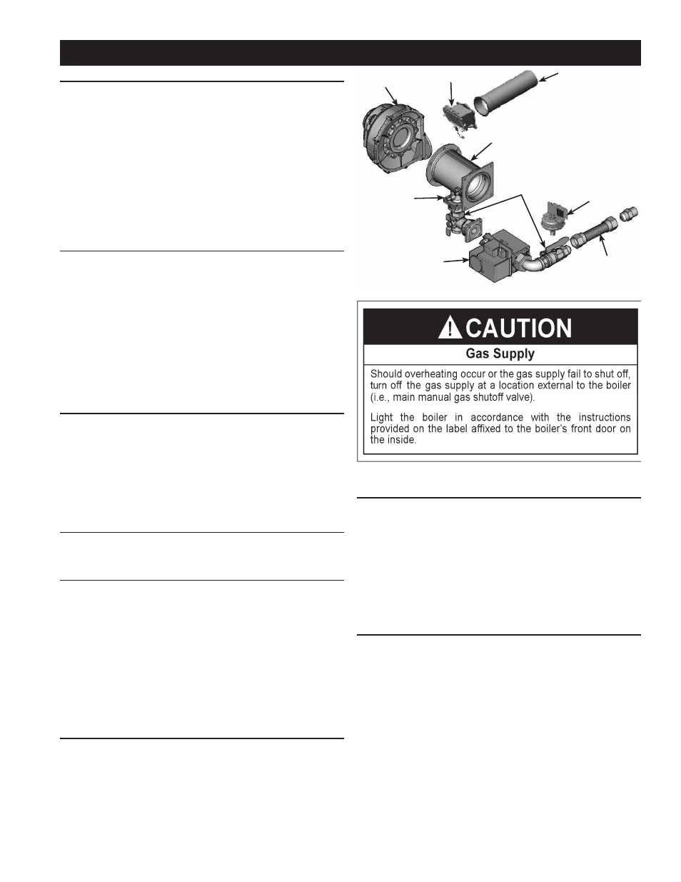
FIGURE 41. GAS TRAIN ASSEMBLY
BURNER
FLAPPER
BLOWER
VENTURI
GAS PRESSURE
SWITCH
FLEX GAS
MANIFOLDS
MANUAL GAS
SHUTOFF VALVE
MODULATING
GAS VALVE
DIFFERENTIAL
MANIFOLD
PRESSURE TAP