Condensate disposal – A.O. Smith 3400 User Manual
Page 38
38
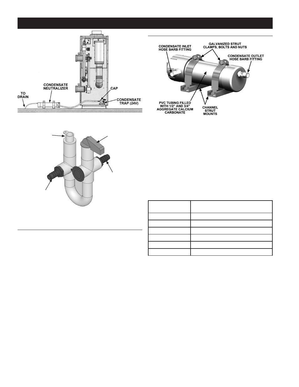
CONDENSATE NEUTRALIZER
The condensate drains from the boiler have pH levels between
4.3 and 5.0. The pH measurement of a fluid is an indicator of
the acidity or alkalinity. Neutral fluids have pH of 7.0. Acid fluids
have pH below 7. Some local codes may require the use of a
condensate neutralizer to raise the pH level of the condensate
leaving the boiler. The condensate neutralizer be must installed
between the boiler and the drain and must be installed lower
than the outlet of the condensate trap as shown in Figure 37. The
Condensate Neutralizer Kit model must be selected with respect
to the boiler's output as mentioned in the Table 16.
TABLE 16. CONDENSATE NEUTRALIZER KIT MODELS
MODELS
(XB)
A. O. SMITH CONDENSATE
NEUTRALIZER KIT NUMBERS
1000
9007961005
1300
9007962005
1700
9007962005
2000
9007962005
2600
9007963005
3400
9007963005
CONDENSATE DISPOSAL
CONDENSATE TRAP
Installation of the Condensate Trap must conform with the
instructions in this manual and local building codes. Condensate
Neutralizer Kits are available. Contact your distributor or Service
Agency. Do not remove, modify or alter the factory installed
condensate trap. Install a commercially available neutralizing kit
if required by the local codes.
The boiler is factory fitted with a 24V condensate trap connected
to the controller. For safety reasons, if the condensate drain is
blocked, the control system will turn off all the firing burners and
bring the boiler to a safe shut down. If there is an air blockage
in the line, vent out the air by removing the cap. Cap acts as an
air vent for releasing any air block on down stream condensate
line. Flexible silicon hose connect from the trap through the
Condensate Neutralizer to the drain.
Due to the highly efficient operation of this unit, condensate is
formed during operation and must be removed by the conden-
sate drain systems. Inspect the condensate drains and tubes at
least once a month and insure they will allow the free flow of
condensate at all times. The system must be inspected more
frequently in cold weather if the drain system is located in an
area, such as along the floor, where freezing tempera tures are
likely to occur. The conden sate drain system must be protected
against freezing. Contact a qualified service technician to inspect
and correct the condition if freezing of the conden sate lines is a
problem.
FIGURE 37. CONDENSATE DISPOSAL SYSTEM
FIGURE 38. CONDENSATE TRAP
FIGURE 39. CONDENSATE NEUTRALIZER
ELECTRICAL SWITCH AND FLOAT
CONDENSATE INLET
FROM THE BOILER
CAP
CONDENSATE OUTLET