Caution – A.O. Smith 3400 User Manual
Page 17
17
A discharge pipe from the relief valve should terminate at an
adequate floor drain. Do not thread, plug, or cap the end of
drain line.
The Discharge Pipe:
• Shall not be smaller in size than the outlet pipe size of the
valve, or have any reducing couplings or other restrictions.
• Shall not be plugged or blocked.
• Shall not be exposed to freezing temperatures.
• Shall be of material listed for hot water distribution.
• Shall be installed so as to allow complete drainage of both
the relief valve and the discharge pipe.
• Must terminate a maximum of six inches above a floor
drain or external to the building. In cold climates, it is
recommended that the discharge pipe be terminated at an
adequate drain inside the building.
• Shall not have any valve or other obstruction between the
relief valve and the drain.
Once the boiler is installed and filled with water and the system
is pressurized, manually test the operation of the pressure relief
valve. See the Maintenance Procedures section of this manual
for instructions.
Your local code authority may have other specific safety relief
valve requirements not covered below. If any pressure relief
valve is re placed, the replace ment valve must com ply with the
current version of the ASME Boiler and Pressure Vessel Code,
Section IV (“HEATING BOILERS”).
XB HYDRONIC BOILERS, are shipped with a 50 psi (345 kPa)
pressure relief valve. This relief valve must be in stalled in the
water outlet as near to the boiler as possi ble.
This ASME-rated valve has a discharge capacity that exceeds
maximum boiler input rating and a pres sure rating that does not
exceed maxi mum working pres sure shown on boiler rating plate.
GAS CONNECTIONS
Make sure the gas on which boiler is to operate is same as that
specified on the rating plate. Do not install boiler if equipped for a
different type of gas. Consult your gas supplier.
This boiler is not intended to operate at gas supply pressure
other than shown on the rating plate. A lock-up or positive shut-
off type regulator must be installed in gas supply line. For proper
gas regulation the lock-up style regulators must be installed no
closer than a minimum of 3 feet (0.9 m) from the boiler and a
maximum of 8 feet (2.4 m) away from the boiler. Exposure to
higher gas supply pressure may cause damage to gas control
valves which can result in fire or explosion. If overpressure
has occurred such as through improper testing of gas lines
or emergency malfunction of supply system, the gas control
valves must be checked for safe operation. Make sure that the
outside vents on supply regulators and the safety vent valves are
protected against blockage. These are parts of the gas supply
system, not boiler. Vent blockage may occur during ice build-up
or snowstorms.
The boiler must be isolated from the gas supply piping system by
closing its main manual gas shut off valve during any pressure
testing of the gas supply piping system at test pressures equal
to or less than 1/2 psig.
Disconnect the boiler and its main manual gas shut-off valve
from the gas supply piping during any pressure testing of the
gas supply system over 1/2 psig. The gas supply line must be
capped when not connected to the boiler.
It is important to guard against gas control valve fouling from
contaminants in the gas ways. Such fouling may cause improper
operation, fire or explosion. If copper supply lines are used they
must be approved for gas service.
When local codes require a main manual shut-off valve outside
the boiler jacket, a suitable main manual shut-off valve must be
installed in a location complying with those codes.
Before attaching gas line be sure that all gas pipe is clean
on inside. To trap any dirt or foreign material in the gas supply
line, a sediment trap must be incorporated in piping. The
sediment trap must be readily accessible and not subject to
freezing conditions. Install in accordance with recommendations
of serving gas supplier. Refer to the current edition of the National
Fuel Gas Code, ANSI Z223.1/NFPA 54 or the Natural Gas and
Propane Installation Code, CAN/CSA B149.1
Size of gas supply piping may be larger than heater connection
on installations where a significant run of piping is required.
To prevent damage, care must be taken not to apply too much
torque when attaching gas supply pipe to boiler gas inlet. When
installing and tightening gas piping use a second wrench to hold
the gas control valve to keep the valve from turning. To prevent
damage to the gas control valve do not use pipe wrench on the
valve body.
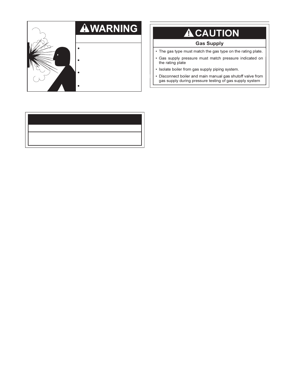
CAUTION
•
Pressure Relief Valve discharge pipe must
terminate at adequate drain.
Water Damage Hazard
Explosion Hazard
Relief Valve must comply with
ASME code.
Properly sized Relief Valve must
be installed in opening provided.
Can result in overheating and
excessive tank pressure.
Can cause serious injury or death.