Local operator interface: display system – A.O. Smith 3400 User Manual
Page 48
48
If any slave under LL Master control is in a Run-Limited condition,
then for some algorithms the LL master can apportion to that
stage the rate that it is actually firing at. Additionally when a
slave imposes its own Run-limited rate, this may trigger the LL
Master to add a stage, if it needs more capacity, or drop a stage
if the run-limiting is providing too much heat (for example if a
stage is running at a higher-than commanded rate due to anti-
condensation).
By adjusting the parameters in an extreme way it is possible
to define add-stage and drop-stage conditions that overlap or
even cross over each other. Certainly it is incorrect to do this,
and it would take a very deliberate and non-accidental act to
accomplish it. But there are two points in this:
1. LL master does not prevent it, and more important;
2. It will not confuse the LL master because it is implemented
as a state machine that is in only one state at a time;
For example:
— If its add-stage action has been triggered, it will remain in this
condition until either a stage has been added,
Or
— The criteria for its being in an add-stage condition is no longer
met; only then will it take another look around to see what state
it should go to next.
DEFINITIONS
Modulating stage: The modulating stage is the Control System
that is receiving varying firing rate requests to track the load.
First stage: This is the Control System that was turned on first,
when no slave Control Systems were firing.
Previous stage: The Control System that was added to those
stages that are firing Just prior to the adding of the Control
System that is under discussion.
Next stage: The Control System that will or might be added as
the next Control System to fire.
Last stage: The Control System that is firing and that was added
the most recently to the group of slaves that are firing. Typically
this is also the modulating stage, however as the load decreases
then the last-added stage will be at its minimum rate and the
previous stage will be modulating.
Lead boiler: The Lead boiler is the Control System that is the
first stage to fire among those stages which are in the equalize
runtime (Lead/Lag) group. If a boiler is in the “Use first” group it
may fire before the Lead boiler fires.
First boiler: A Control System may be assigned to any of three
groups: “Use First”, “Equalize Runtime”, or “Use Last”. If one or
more Control Systems are in the “Use First” category, then one
of these (the one with the lowest sequence number) will always
be the first boiler to fire. If there is no Control System in the “Use
First” category and one or more are in the “Equalize Runtime”
category, then the First boiler is also the Lead boiler.
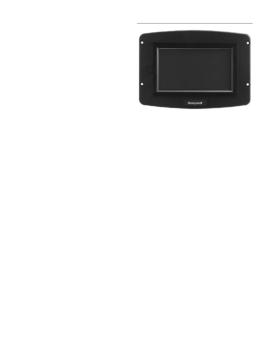
LOCAL OPERATOR INTERFACE: DISPLAY SYSTEM
FIGURE 47. BURNER CONTROL S7999D DISPLAY SYSTEM
The S7999D is a microprocessor-based color touch-screen
Operator Interface (OI) display that provides an operator interface
for monitoring and configuring parameters in the Burner Control
system.
The S7999D can be used to monitor an individual boiler but is also
used for multiple boiler applications in a lead/lag arrangement. It
consists of 2 RS485 ports (COM 1 & COM 2) and USB port.
The S7999D display can be flush front or behind mounted into
a panel cutout. Wiring connections to the S7999D are through a
removable 8-pin wiring connector.
FEATURES
•
Individual boiler status, configuration, history, and
diagnostics.
•
Allows configuration and monitoring of the Burner Control
Controls burner control sequence, flame signal, diagnostics,
historical files, and faults.
•
S7999D OI Display only:
• Allows switching view between multiple burners.
• Allows viewing Lead-Lag Master.
• Real-time data trending analysis and transferring saved
trend data to Excel spreadsheet.
• 7” 800 x 480, 24 bit high resolution color LCD touch
screen for clarity.
• Audio output with integral speaker for sound output.
• Adjustable backlight control.
• Real time clock with coin-cell battery back up (CR2032).
• S7999D has Black Border.
• Volume control.
• Screen Capture function to capture screen images.
• USB port for file transfers and software updates
• 2 RS-485 (COM1 & 2) ports for Modbus™ interface to
Burner controls and BAS Gateway.
• Windows® CE 6.0 Operating System.
• 8-pin connector, back-up battery and mounting hardware
are provided.