A.O. Smith 3400 User Manual
Page 50
50
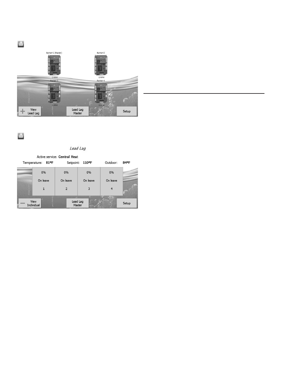
The Home page also includes buttons for Lead Lag configuration
when lead lag master and slave in the Burner control is
enabled. Pressing the Setup button on the Home page displays
miscellaneous setup and diagnostic functions. It also contains
the setup configuration for BAS applications.
The “Control snapshot” button allows the user to dump the current
status and/or configuration settings of any Burner controller into a
text document. The text document can be viewed on the display,
saved to flash for later viewing, and can be written to a USB stick
for viewing on a PC or file transfer. Pressing the Burner control
icon opens that control’s status page. Go to “Configure” button
to continue.
PAGE NAVIGATION
The Burner Control System OI Displays present information
and options in a paged manner. Pages are displayed in a tree
structure in which the user navigates up and down to arrive at
the desired Function (see Figure 51). The page descriptions
are provided below so that you can understand the purpose of
each and view the selections, parameters, and information that
is available or required on each.
COMMON OI DISPLAY PAGE SYMBOLS
Most pages have a Home button in the top-left corner of the
screen and a Back button in the top-right corner of the screen.
The Home button returns the user to the Home page and
terminates any operation in progress. The Back button returns
the user to the previous page.
Two other icons may be noticed near the boiler name.
A camera button is for screen snapshot use. Up to 16 snapshots
can be stored in the display and can be copied to a USB memory
stick.
A padlock indicates the operator is not currently logged in (may
have been timed out) and a password is needed to change the
setting. An unlocked padlock indicates the password has been
entered and the operator has logged into system successfully.
STATUS OR HOME PAGE
A status (summary) page (Figure 52 on Page 52) is displayed
when the S7999D display is connected. This status page appears
on the S7999D when the Burner control icon is pressed on the
“Home” page. The status page displays the current condition
of the burner control and displays some of the more important
configuration settings.
The initial status page displayed contains summary status
information as shown in Figure 52. Any status information not
applicable for the installation is grayed/blanked out on the screen.
Buttons on this screen include:
• Configure: used to configure the burner control
(password protected and all pre-configured).
• Operation: used to perform daily or frequent functions
with the burner control, such as setpoint adjustment, etc.
• Diagnostic: used to view burner control diagnostic
information (for servicing and temperature setting
purpose only).
• Details: used to view burner control detail status
information.
• History: used to view burner control history.
• Pump: used to expand the pump status information.
• Modulation: used to toggle between status displays:
pump, setpoints, and modulation.
HOME PAGE (S7999D OI DISPLAY)
Make sure a screen similar to Figure 49 appears after the OI
Display has completely powered up.
FIGURE 49. S7999D HOME PAGE
(BOILER 1 IN NORMAL OPERATION)
FIGURE 50. S7999D LEAD LAG HOME PAGE
On System applications, each Burner Control System is
represented on the Home page by an icon and name. Pressing
the icon allows the user to zoom in on that burner and see its
specific details. These details are provided on a new page, which
can include additional buttons that display additional detail and
operation information, which itself leads to other pages. The
pages are traversed in a tree structure method, as shown in
Figure 51 on Page 51.
The Control System icons will appear in one of four colors
indicating the boiler status.
• Blue: Normal operation
• Red: Lockout condition
• Gray: Communication error (disconnected or powered
off)
• Yellow: Holding mode
Up to 8 Systems can be displayed on the Home page. The name
of each burner is displayed next to the Control System icon button.
When Lead Lag is enabled, the system header temperature and
firing rate are displayed for each System. When the burner is in
standby or not firing the firing rate is not displayed.
NOTE: The boiler name may be cut off on the Home page when
all icons are present.