A.O. Smith 3400 User Manual
Page 14
14
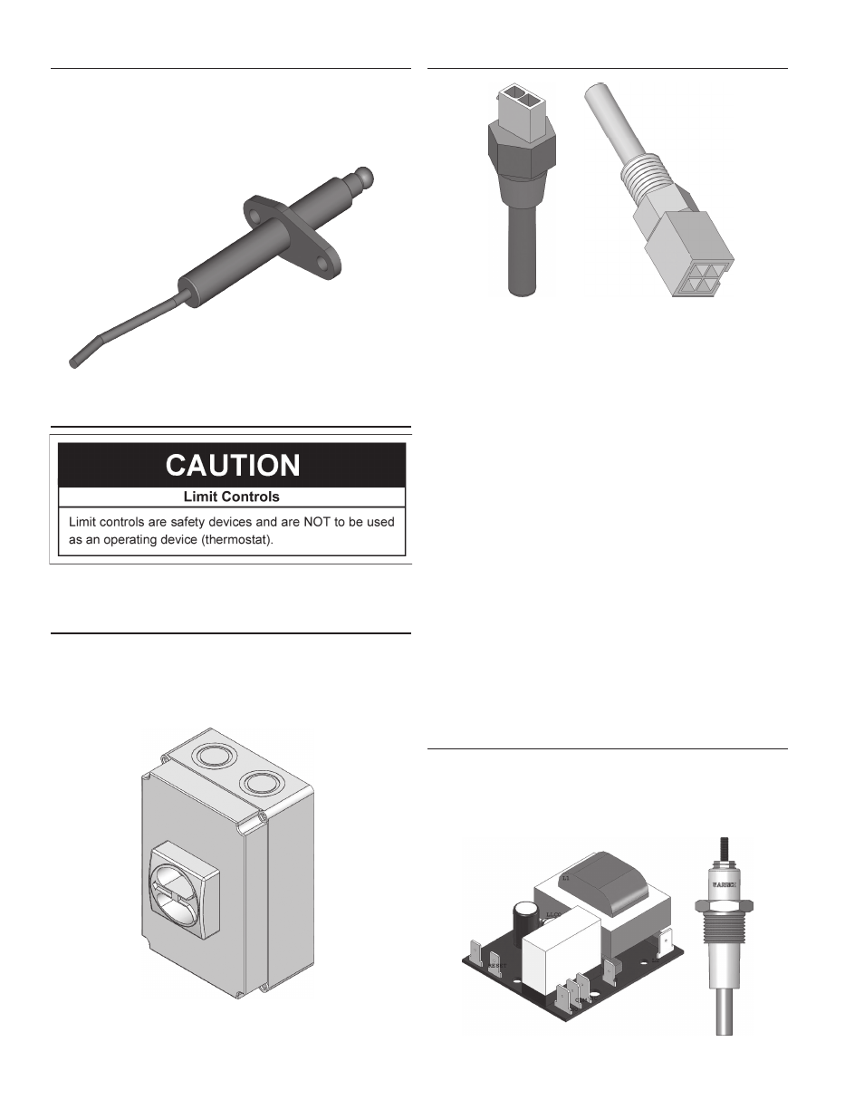
FLAME SENSOR
Each burner is equipped with a flame sensor to detect the
presence of the burner flames at high and low fire conditions. If
no flame is sensed, the gas control valve will close automatically.
The voltage sensed by the flame sensor will also be displayed on
the Burner Screen.
FIGURE 10. FLAME SENSOR
WATER TEMPERATURE LIMIT CONTROLS
The XB models incorporate an outlet water sensor having dual
sensors, that are factory set at 210°F (99°C).
MAIN POWER SUPPLY SWITCH
The main power supply switch is a padlockable switch. This switch
pro vides 120V from the power supply to the boiler.
This switch needs to be turned off when servicing the boiler.
NOTE: The Enable/Disable (Interlock) Switch on the front of
the boiler does not interrupt electrical power to the boiler.
FIGURE 11. MAIN POWER SUPPLY SWITCH
WATER TEMPERATURE SENSORS
FIGURE 12. WATER TEMPERATURE SENSORS
Temperature sensors are threaded immersion probes.
Temperature probes have embedded temperature sensors
(thermistors). The boiler’s control system monitors these sensors
to determine water temperature at various points in the system.
INLET AND OUTLET TEMPERATURE SENSORS
All models have two inlet and two outlet temperature sensors
for each heat exchanger, factory installed to monitor the water
temperature entering and leaving the boiler. The Inlet Probe is
a temperature sensor only and has two leads. The Outlet probe
also contains the manual reset high temperature limit switch
on the display and has four leads. The control system displays
the Inlet and Outlet water temperatures sensed from these two
sensors on the default Temperatures screen.
REMOTE SENSORS
All models are supplied from the factory with a remote sensor.
The remote sensor is used to control system water temperature
for a single boiler in the return line from a primary/secondary
hydronic heating system.
The boiler will modulate its firing rate in response to the
actual system temperature and load conditions. The control
system displays the temperature sensed from the remote sensor
as the “Lead Lag” temperature on the default Temperatures
screen.
LOW WATER CUTOFF DEVICE (LWCO)
Low water cutoff device is normally a closed switch that opens
when water drops below a preset level. Each model is equipped
with a factory installed LWCO. LWCO board is connected to the
electronic panel, whereas the sensor probe is connected to the
heat exchanger.
FIGURE 13. LWCO BOARD AND PROBE