Figure 72 – A.O. Smith 3400 User Manual
Page 58
58
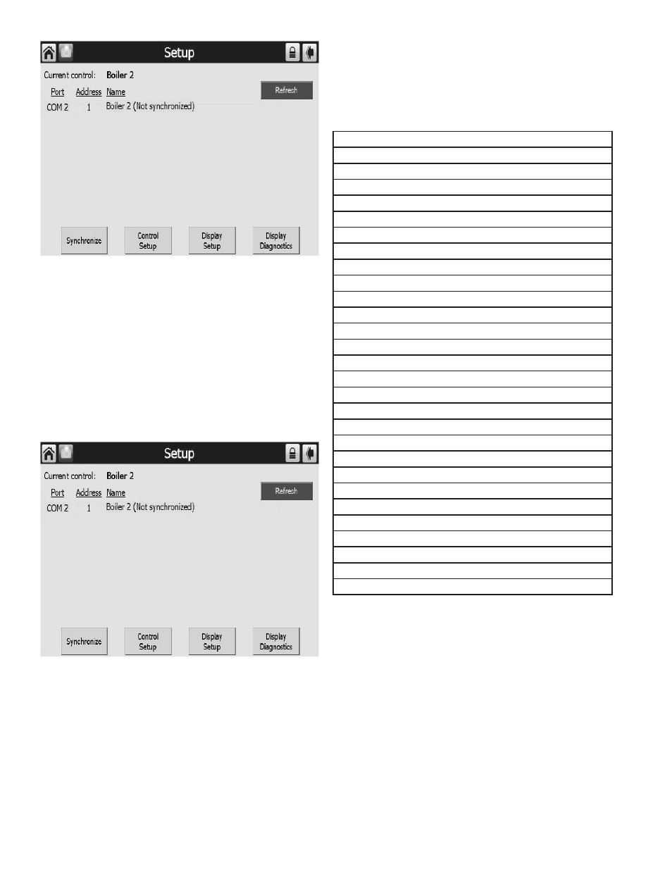
FIGURE 72. SYSTEM CONFIGURATION PAGE
SYSTEM SYNCHRONIZATION (S7999D OI DISPLAY ONLY)
The user can manually synchronize configuration data from the
connected controls at any time.
A new control is visible when configuration and status data is
gathered from it. This collection procedure takes a few minutes.
The control is marked as “Unknown” when no configuration
information exists. Normally, control configuration data collection
only needs to be performed when the control is initially installed.
However, a re synchronization is necessary after the OI Display
is reset. See Figure 73.
The user presses the Synchronize button to begin synchronization
with the control. See Figure 73.
Status of the synchronization is reflected in the dialog box. The
synchronization can be aborted by selecting the Cancel button.
FIGURE 73. SYSTEM SYNCHRONIZATION
CONFIGURATION
The Burner Control can be configured from the OI Display. The
control configuration is grouped into the functional groups as
HYDRONIC CONTROL
System Identification and Access
CH - Central Heat
Outdoor Reset
DHW - Domestic Hot Water
DHW Storage
DHW Plate
Warm Weather Shutdown
Demand Priority
Modulation Configuration
Pump Configuration
Statistics Configuration
High Limit
Stack Limit
Delta T Limits
T-Rise Limit
Heat Exchanger High Limit
Anti-condensation
Frost Protection Configuration
Annunciation Configuration
Burner Control Interlocks
Burner Control Timings and Rates
Burner Control Ignition
Burner Control Flame Failure
System Configuration
Fan Configuration
Sensor Configuration
Lead Lag Slave Configuration
Lead Lag Master Configuration
Most of this configurations are already performed by the qualified
service technician or at A. O. Smith. Each functional group is
displayed on the Configuration menu page.
Parameters in functional groups that are not applicable for
the installation can be ignored. In some cases, features in a
functional group are disabled by default and are enabled when
needed for the installation.
TABLE 21. FUNCTIONAL CONFIGURATION GROUPS