A.O. Smith 3400 User Manual
Page 44
44
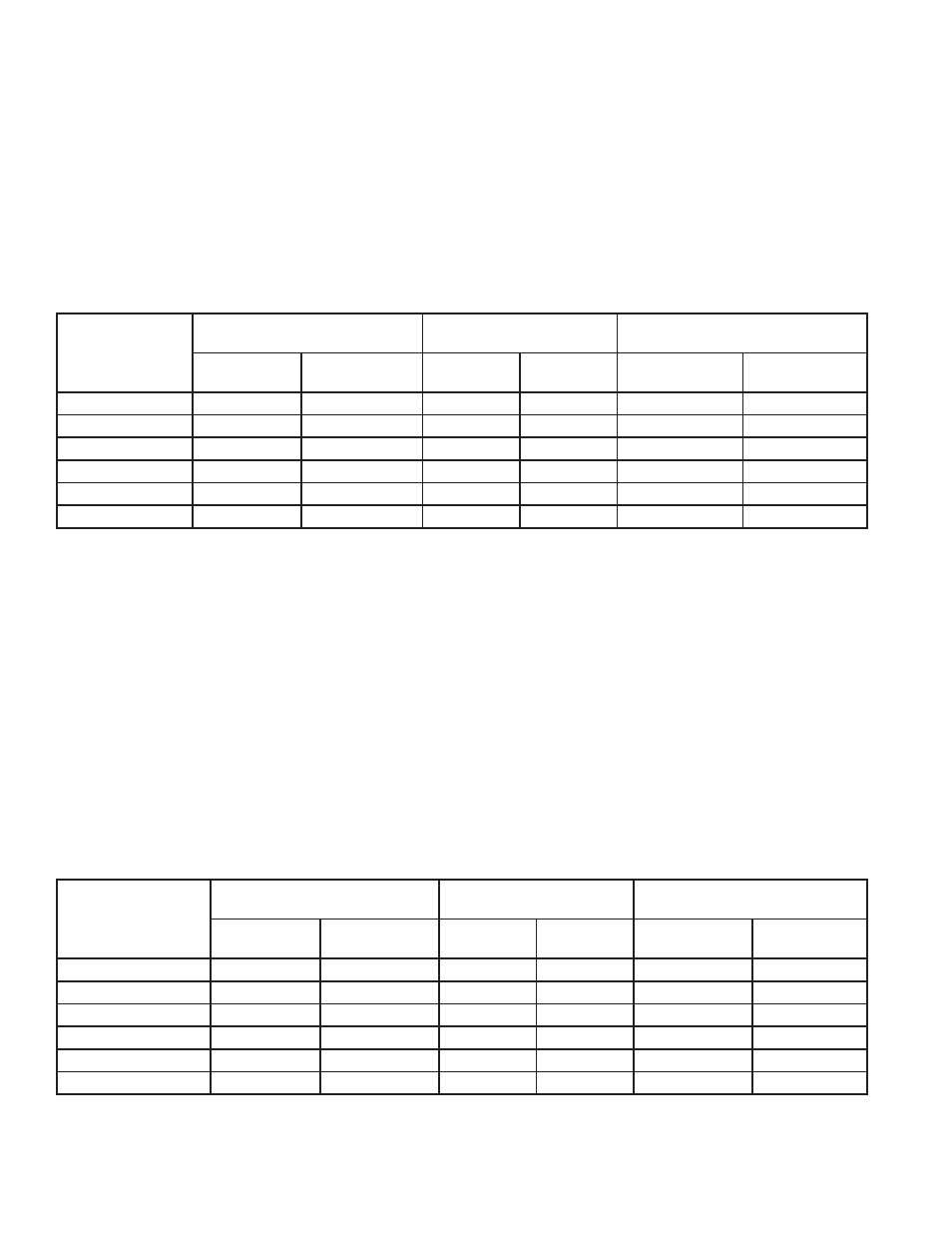
HIGH FIRING RATE SETTING
Set the boiler to the high firing rate by setting the High Firing Rate RPM as described below. Check combustion readings using a
combustion analyzer. If combustion readings are not in accordance with the chart below adjust the gas control valve as follows:
remove the flat, round, blue plastic cap from the cover (see Figure 8 on Page 13). Using a 3 mm (7/64”) hex wrench, turn the
adjustment screw counterclockwise to increase or clockwise to decrease gas flow and achieve the desired CO
2
level. Make sure
to close the boiler door after adjusting the gas valve for direct vent configurations. Refer to the Table 17 for correct settings. There
will be a slight time delay between the adjustment and the response of the CO
2
measuring instrument. Adjust the settings in small
increments and allow the combustion readings to stabilize before readjusting. When desired adjustments are complete, reinstall the
blue plastic cap on the cover. Combustion samples should be taken in the stack within two feet of the boiler. The carbon monoxide
(CO) values in the combustion sample should not exceed 150 PPM under any circumstances. Contact OEM for any abnormal
conditions leading to excessive CO above 150 PPM.
MODELS (XB)
RPM
(APPROXIMATE FACTORY SET)
CO
2
*MANIFOLD PRESSURE
INCHES W.C (KPA)
NATURAL
GAS
PROPANE
NATURAL
GAS
PROPANE
NATURAL GAS
PROPANE
1000
4450
4750
8.5 - 9.2%
9.3 - 10.2%
-3.5 (-0.87)
-4.7 (-1.17)
1300
4850
5100
8.5 - 9.2%
9.3 - 10.2%
-3.0 (-0.75)
-3.6 (-0.89)
1700
5700
5700
8.5 - 9.2%
9.3 - 10.2%
-3.6 (-0.89)
-4.4 (-1.09)
2000
4700
4750
8.5 - 9.2%
9.3 - 10.2%
-3.9 (0.97)
-4.9 (-1.22)
2600
5200
5100
8.5 - 9.2%
9.3 - 10.2%
-3.3 (-0.82)
-3.6 (-0.89)
3400
5700
5700
8.5 - 9.2%
9.3 - 10.2%
-3.5 (-0.87)
-4.4 (-1.09)
LOW FIRING RATE SETTING
Set the boiler to the low firing rate by setting the Low Firing Rate RPM as described below. Check combustion readings using a
combustion analyzer. If combustion readings are not in accordance with the chart shown below adjust as follows: remove the cap on
the gas regulator using a slotted screwdriver (see Figure 8 on Page 13). This will expose the offset adjustment screw. Using a TORX
®
T40 or a 5 mm hex wrench, carefully adjust the low fire gas setting to achieve the CO
2
Adjustments to the offset pressure regulators should not exceed 1/4 turn at a time before allowing the readings to respond and
stabilize.
After proper low fire offset adjustment is made, reinstall the slotted cap on the regulator.
Following all gas control valve adjustments, check for proper light-off and verify correct fuel/air mix and combustion quality throughout
the entire firing range (from lowest to highest fan speed).
NOTE: The rotation of the Low Fire adjustment is opposite of the High Fire as follows: Clockwise rotation increases gas flow,
counterclockwise rotation decreases gas flow. Make sure the Manual Mode is set back to Automatic Mode to each of the burners,
once the required settings are done. Turn off the individual burner before proceeding to the next burner settings. Depending on the
boiler size and capacity, the flame voltage will be between 10-15 volts for low fire and 25-32 volts for high fire settings. Check for gas
valve settings and combustion for varied voltage levels.
MODELS (XB)
RPM
(APPROXIMATE FACTORY SET)
CO
2
*MANIFOLD PRESSURE
INCHES W.C (KPA)
NATURAL
GAS
PROPANE
NATURAL
GAS
PROPANE
NATURAL GAS
PROPANE
1000
1650
1540
7.3 - 8.2%
8.4 - 8.8%
-0.3 (-0.07)
-0.25 (-0.06)
1300
1650
1600
7.3 - 8.2%
8.4 - 8.8%
-0.2 (-0.05)
-0.14 (-0.03)
1700
1700
1700
7.3 - 8.2%
8.4 - 8.8%
-0.2 (-0.05)
-0.23 (-0.05)
2000
1550
1540
7.3 - 8.2%
8.4 - 8.8%
-0.3 (-0.07)
-0.31 (-0.07)
2600
1700
1600
7.3 - 8.2%
8.4 - 8.8%
-0.2 (-0.05)
-0.14 (-0.03)
3400
1700
1700
7.3 - 8.2%
8.4 - 8.8%
-0.2 (-0.05)
-0.23 (-0.05)
* NOTE: Values listed in Table 17 and Table 18 are tested under laboratory conditions with minimum vent length. Values may slightly vary depending on
ambient conditions and field equipment accuracy.
TABLE 17. HIGH FIRE RATE
TABLE 18. LOW FIRE RATE