FUTEK VCal Sensor Verification User Manual
Page 44
Futek Advanced Sensor Technology – Futek VCal™Documentation
Rev. 1.8.0
07/26/05
©Futek Advanced Sensor Technology 2005
44
Now we need to talk a little about the three types of testing which are available to you in the Calibration interface. I told you a little earlier that
we would give some more details about the Main Test, the Time Test, and the Signature Test. The Main Test is the default type of test, and
iwhat type of test you will perform if you do not select either Time or Signature Test on the pull-down menu available from the hand signing icon in
the row of command buttons along the top of the interface window (see page 30 for location).
Main Test
The Main Test is the default, or standard calibration type. It consists of you entering all the required information asked for on the Information
Tabs sections of the interface (the Info, Initial, Setup, and Test tabs), followed by you pressing
Begin Test
on the Setup tab,, and then taking
a first zero reading with your sensor unfixtured on the Test tab. You would then fixture your sensor, click into the Output box to the right of the
first Load point (0) in the Test Grid, and press
Enter
. After this you would proceed through the load points indicated on the Load column of the
Test Grid, after clicking into each of the output boxes in a progressive fashion (0 through full scale, then final zero still fixtured) in the Test Grid.
After this you would take a final zero reading with your sensor unfixtured on the Test tab, and possibly view your Uncertainty and Zero Return
values on the Test tab. You would then have the options of saving, graphing, or printing certificates and reports stating the results of your
calibrations and tests.
Time Test
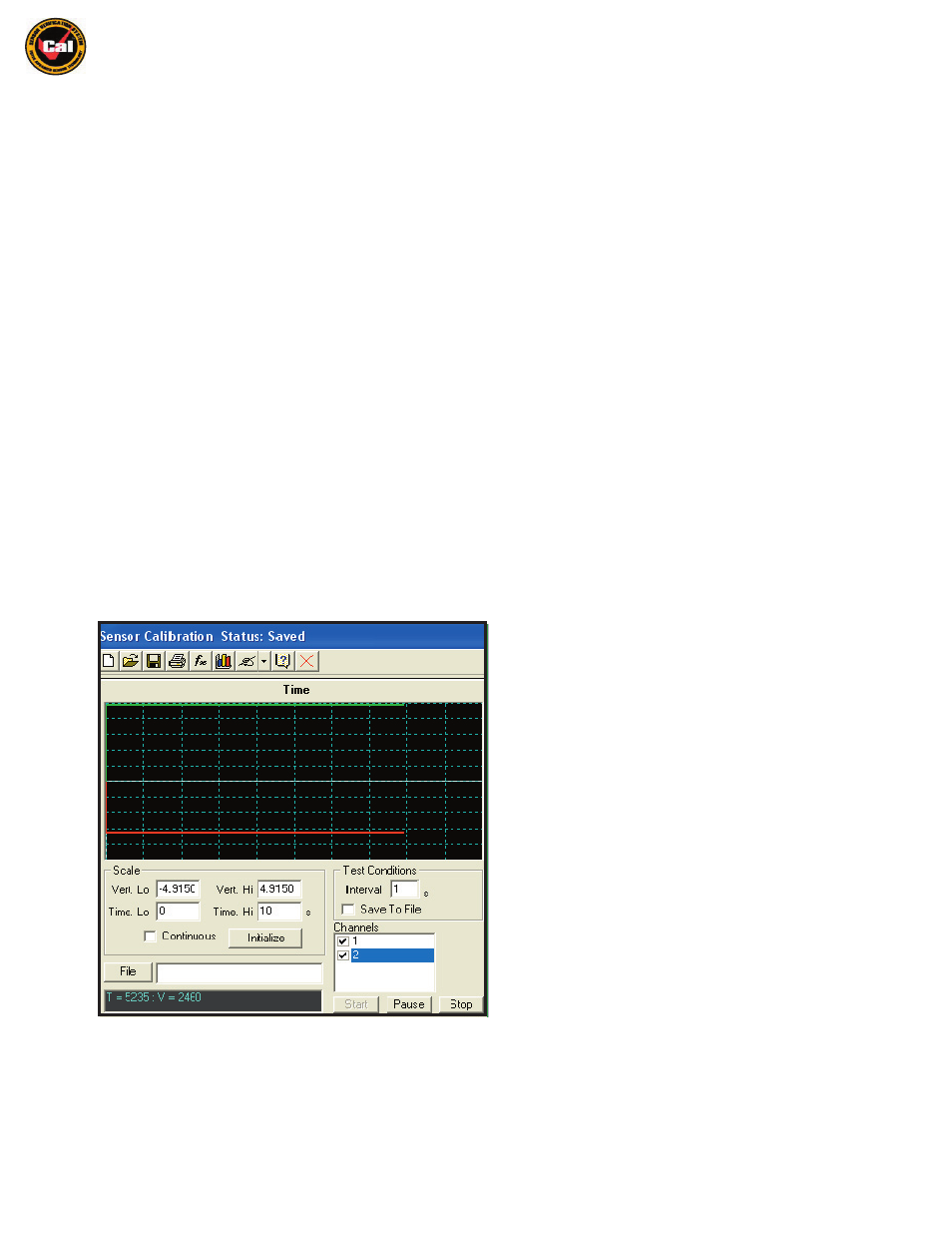
Selecting the Time Test option in the pull-down menu brings up the following screen, where you can perform VCal™’s Time Test calibration.
Here you are able to run a timed test with readings taken at pre-defined intervals, watch the graphic display of the outputs in real time, and
also save the results of these timed tests to a file of your choosing. The screen below and the descriptive text that accompany it will give you an
overview of the Time Test interface; more detailed instructions for using this interface will be given in the Instructions For Performing
A Calibration Verification section of this Manual. (
pg. 47
)
Vert Lo -
This setting determines the lower output limit which will
be displayed on the Time Test Grid. This output is displayed in
the same units you have chosen for output.
Vert Hi -
This setting determines the upper output limit which will
be displayed on the Time Test Grid. This output is displayed in the
same units you have chosen for output.
Time Lo -
This setting determines the start time for your test run.
Please note that negative start times aren’t valid, you must start
your test at 0 seconds start time or higher.
Time Hi -
This setting determines the end time for your test, or if
your start time is 0, the length of your test. Please note that all
end, as well as start times are in seconds. You may also choose
to make your test continuous (no end time) by selecting the
Continuous checkbox.
Initialize -
This button initializes the test grid with traces for the
Channels you have selected in the Channels section.
Interval -
This option allows you to set at what interval VCal™
will take readings. These can be set at any increment of 0.1s. For
example; if you have Time Hi set to 10s, and your Interval set to
0.1s, then VCal™ will take 100 readings during the test.
Save To File -
This option allows you to save the data from your
test to a spreadsheet application file.
File -
Click this button and point the window at the location of the file where you wish to save your data.
Channels -
Here you select which channels you wish to have displayed on the Grid during the test.
Start / Pause / Stop -
These buttons give you contol over your test by allowing you to Start, Pause, or Stop your test at any time.