Iv. operational instructions - “how to – FUTEK VCal Sensor Verification User Manual
Page 40
Futek Advanced Sensor Technology – Futek VCal™Documentation
Rev. 1.8.0
07/26/05
©Futek Advanced Sensor Technology 2005
40
IV. Operational Instructions - “How To”
Instructions For Calibrating A Reference Cell
Now that we have explored the layout of the Reference Sensor and Calibration interfaces; let’s walk through an instructive example calibration
using your Futek VCal™ system and Futek Reference Sensor:
1. The first thing you will want to do is to open the Reference Sensor interface by clicking on the Reference Sensor icon,
and
then connect your VCal™ Reference Sensor to the desired channel (usually this is channel 1). Once VCal™ has recognized the sensor ID and
displayed it at the top of the Channel Display window (4 - 5 seconds), you should press the
Gross Button
(either on the Channel Display or Test
Grid windows) to remove any previous tare values which may still be in memory.
2. Next you should press the “Clear Scaling” button on the Channel Display window; this will clear any previous scaling factors and also set
the default output readings to mV/V. If this is not done your test will not be a valid calibration.
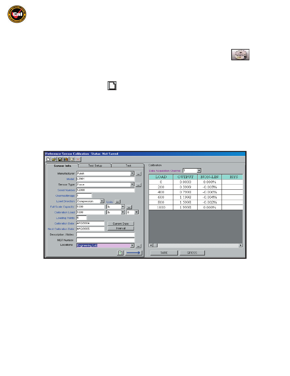
3. Next, you would need to enter all relevant information on the Sensor Info and Test Setup tabs (VCal™ will return an error message
if you attempt to initialize a test without providing all required information on each tab). For a description of each required field you
may review the information on pages 26 - 27.
4. When you have filled in all required fields on the Sensor and Test Setup tabs; then choose either “
Linearity
” OR “
Hysteresis
” on the
Test Setup Tab, and click on the
Initialize Test
button. This will fill in the Test Grid with the proper load points for your calibration.
The following is an example of a window similar to what you should see on your screen:
5. Next, you would need to fixture your sensor (see pages
49-50
for fixturing examples), and then tare your load cell by pressing the
Tare
button
(this puts all offsets in place and zeroes your display). You are now ready to begin taking readings. Click in the first Output box in the test grid,
next to zero, and press Enter to take your first zero reading. Next, load the cell to the first load point (50 lbs in this example), click in the output
box next to 50 and press Enter and VCal™ will take the reading. Repeat this process for each load point in the Test Grid.
6. Once you have taken the last reading, the “Linearize” button (on Test tab) will begin flashing; at this point you have the choice of whether
or not you wish to
Linearize
the load cell. A
Hysteresis
correction is also possible, for this correction you must select the hysteresis
option on the Test Setup tab before beginning a test. The correction works by applying a linearization factor on the loading and
unloading of the cell. Hysteresis corrections are only applied when doing a calibration on the Sensor Calibration window. Just click the
Linearize button to apply the corrections. The first linearization coefficients are applied on the loading of the sensor up to full scale.
After that, the hysteresis coefficients are applied during the unloading of the sensor.
7. Under Scaling, enter the rated output of the load cell: For example if a 5000 lb cell is rated at 2.000 mV/V (from cert or test), you should
enter 2.000 mV/V even if you are only loading to a calibration load of 500 lbs. Enter your Default Decimal Points to display. Over Load
Threshold determines at what level VCal™ will issue a red, flashing Sensor Overload Warning. Over Range Threshold determines at what
level VCal™ will issue a yellow, flashing Outside Calibration Range Warning.