FUTEK VCal Sensor Verification User Manual
Page 26
Futek Advanced Sensor Technology – Futek VCal™Documentation
Rev. 1.8.0
07/26/05
©Futek Advanced Sensor Technology 2005
26
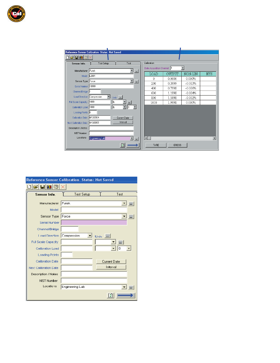
The rest of the Reference Sensor Calibration interface is broken into two, basic sections; the
Information Tabs
, and the
Test Grid
sections . . .
Information Tabs
Section
Test Grid
Section
Information Tabs Section -
There are three main windows to the
Information Tabs
Section . . .
First is the
Sensor Info
tab; this is where you will enter the descriptive information on the Reference Sensor you are calibrating. Please note that
Text Box Titles which are displayed in
Blue
are required if you wish to perform a calibration or test.
Manufacturer - This is where you enter the name of the
manufacturer of the load cell you are calibrating. Clicking the down
arrow icon at the right of the text box displays a pull - down menu
which lists all Manufacturers you have saved in the Management
Tools section of VCal™. (
see pg. 36
) Clicking the icon with three
periods will talke you to the section of Management Tools where you
save Manufacturer Names.
Model -
This is where you enter the
Model
number of your sensor.
Sensor Type - This is where you enter the type of sensor you wish to
test or calibrate. Again, you have icons for accessing the pull - down
menu of saved sensor types, and for going to the Sensor Types in the
Management Tools section of VCal™. (
see pg. 37
)
Serial Number -
This is where you enter the
Serial Number
of the
reference sensor you wish to calibrate.
Channel/Bridge -
This is where you enter the
Channel
or
Bridge
you
wish to use (on multi-channel sensors) Default is 1.
Load Direction -
This is where you specify which
Direction
you wish to
apply your load in. Again, there are icons for accessing the pulldown
menu of saved
Load Directions
and for going directly to the saved load
direction
Units
in the Management Tools section.(
p. 38
)
Full Scale Capacity -
This is where you enter the
Full Scale Capacity
(max load) for your sensor. Again, there is the familiar, pull-down menu of
saved load units, and an icon for going directly to the saved
Conversion Factors
in the Management Tools section. (
p. 37
)
Calibration Load -
This is where you designate the
Maximum Load
you wish to apply during this test. Please note that this amount may or may
not be the same as the Full Scale Capacity for your sensor. Again, there is an icon for the pull-down menu for Load Units, and also for 26 decimal
places in the Calibration Load values.