FUTEK VCal Sensor Verification User Manual
Page 21
Futek Advanced Sensor Technology – Futek VCal™Documentation
Rev. 1.8.0
07/26/05
©Futek Advanced Sensor Technology 2005
21
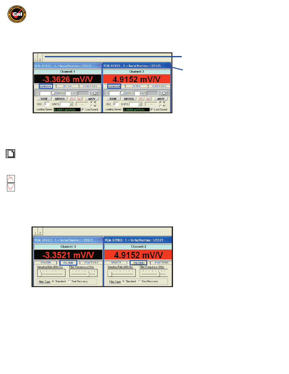
Channel Display Window Options
The Channel Display Windows are where your test readings are displayed, and also where you set your initial configuration settings for your
tests and verifications. There are three main tabs to the Channel Display Windows; (1) the Sensor Tab; (2) the Filter Tab; and (3) the
Functions Tab:
Under the Sensor Tab
-
You will find the following tools and command buttons (from left to right, and top to bottom):
ID Input Box -
If your sensor is equipped with the Futek VCal™ auto-recognition ID chip the sensor serial number will appear here, or you may
enter a sensor serial number here manually. The checkbox allows you to select/unselect the Auto Read function.
(pg. 32)
BRDG -
Bypass ID-Chip Polling: Use when calibrating reference sensors with no ID chip.
CAP -
This box lets you enter a capacity for the sensor you are testing or verifying on this channel.
Clear the Scaling -
Clears any scaling factor which may currently be loaded. Used for creating a new calibration curve for calibrating your
Reference Sensors.
Tare -
The zeroed reading of your sensor with all offsets nulled.
Gross -
The untared reading of your sensor with all offsets still in place.
Set to Peak Mode -
Takes a peak reading, unselect to clear the peak reading.
Set to Valley Mode -
Takes a valley reading, unselect to clear the valley reading.
mV/V -
Shows you the current mV/V reading of the sensor without clearing the scaling factor, used to verify that mV/V matches load.
DEC -
Allows you to define the decimal places displayed.
F / C -
Allows you to define whether test temperature is displayed in Fahrenheit or Celsius.
Loading Speed -
Allows you to monitor and subsequently control, the speed with which your load, and thus output, changes.
UNITS
-
Allows you to change the displayed units in real time.
Under the Filter Tab
-
You will find the following available settings, which you may customize to your needs by simply adjusting the sliding
bars to the value you require.
Sampling Rate -
This setting is used to adjust the internal sampling rate, the eight available rates are: 4.688; 9.375; 18.75;
37.5; 75; 150; 300; and 600 readings per second. Please note that filter settings and system overhead in general, will affect
the VCal™ actual throughput.
Filter Frequency -
This setting is used to adjust the frequency of the low pass filter. On Standard Filter the following settings are
available: 40; 18; 8; 4; 2; 1; 0.5; and 0.25 Hz. On Fast Recovery Filter the following settings are available: 18; 11; 9; 7; 5; 4; 3.5;
3; and 2.5 Hz. The filter setting determines how fast the system will respond to changes in load.
Filter Type -
This setting allows you to choose between Standard and FIR Fast Recovery filters. Transient recovery of this
filter is independent of the filter’s cutoff frequency. The filter setting determines how fast the system will respond to changes in load.
Hide or Unhide the Channel Display Window
You may also drag and drop the windows to
to any convenient location on the screen by
grabbing the blue title bar.