FUTEK VCal Sensor Verification User Manual
Page 28
Futek Advanced Sensor Technology – Futek VCal™Documentation
Rev. 1.8.0
07/26/05
©Futek Advanced Sensor Technology 2005
28
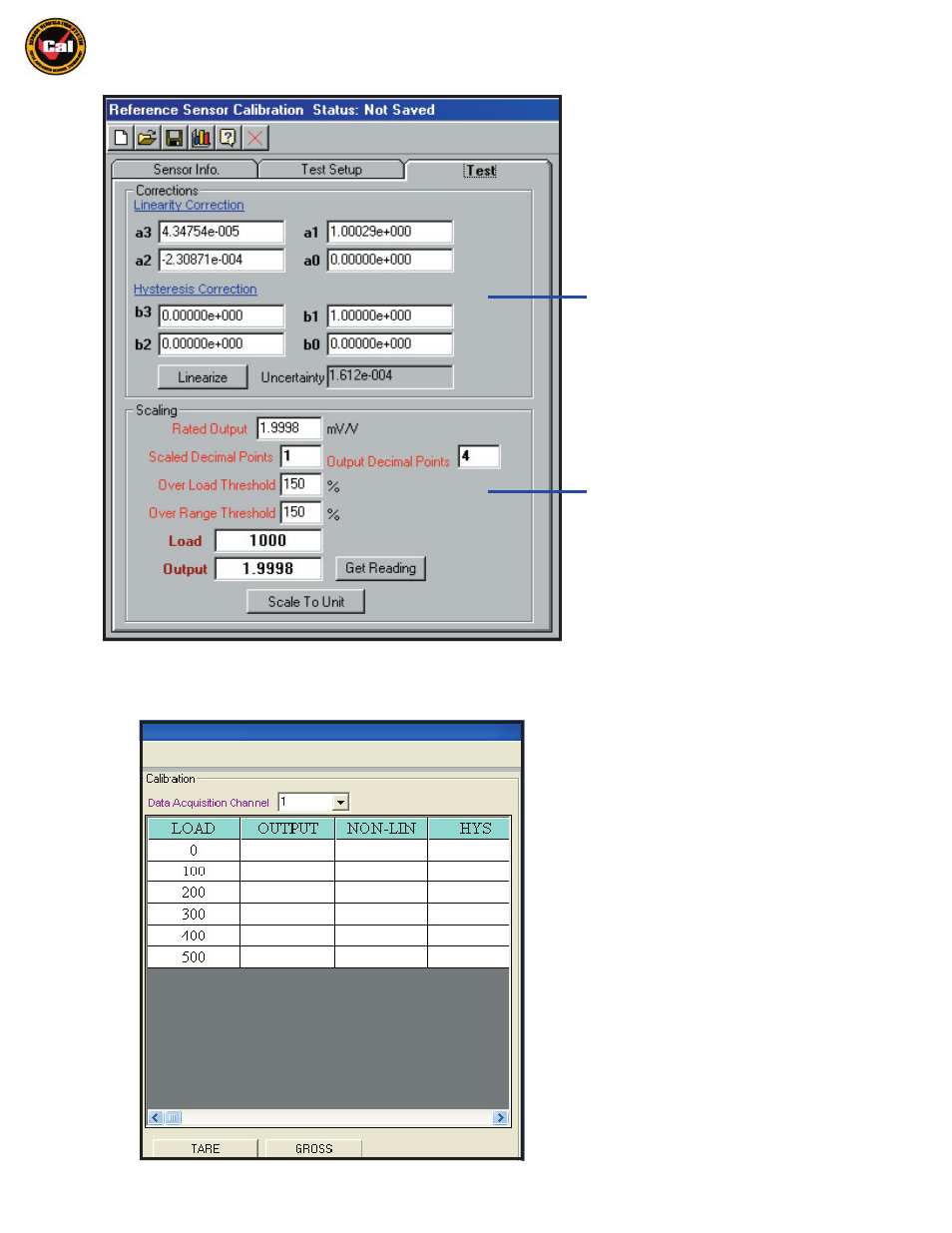
The final window under the
Information Tabs Window
- i
s the
Test Tab Window.
This window provides you
some options for applying correction factors and
uncertainty values to your test to provide added
confidence in the accuracy of your results.
The
Corrections
section of this window is where
you can view the
Linearization Coefficients
and
Uncertainty Values f
or your calibration. Once you
have completed a test you can come to this tab
and click the
Linearize Button
to view these values.
Please note that
Hysteresis Correction
values will
only be calculated if
Hysteresis
was selected on the
Test Setup Tab
under Test Conditions.
The
Scaling
section of this window is where you
can set
Over Load
and
Over Range
warning points,
as well as set
Scaling Factors
. You simply enter the
Rated Output
of your sensor, load to the desired
calibration load,
take a current output reading,
and then press
Scale To Unit
(more detail will be
given in the Instructions section). The number of
decimal points for pre-calibrated reference sensor
output can be entered in the
Output Decimal Points
textbox.
Calibration Test Grid
The other half of the Reference Sensor interface
is
The
C alibration Test Grid.
The
Data Acquisition Channel
is the channel you
have your Reference Sensor connected to.
The
Test Grid
is where you will perform your tests
and view your test results.
The Tare Button allows you to utilize offsets and
zero the unloaded output.
The Gross Button allows you to take an untared
reading with all offsets in place.