FUTEK VCal Sensor Verification User Manual
Page 32
Futek Advanced Sensor Technology – Futek VCal™Documentation
Rev. 1.8.0
07/26/05
©Futek Advanced Sensor Technology 2005
32
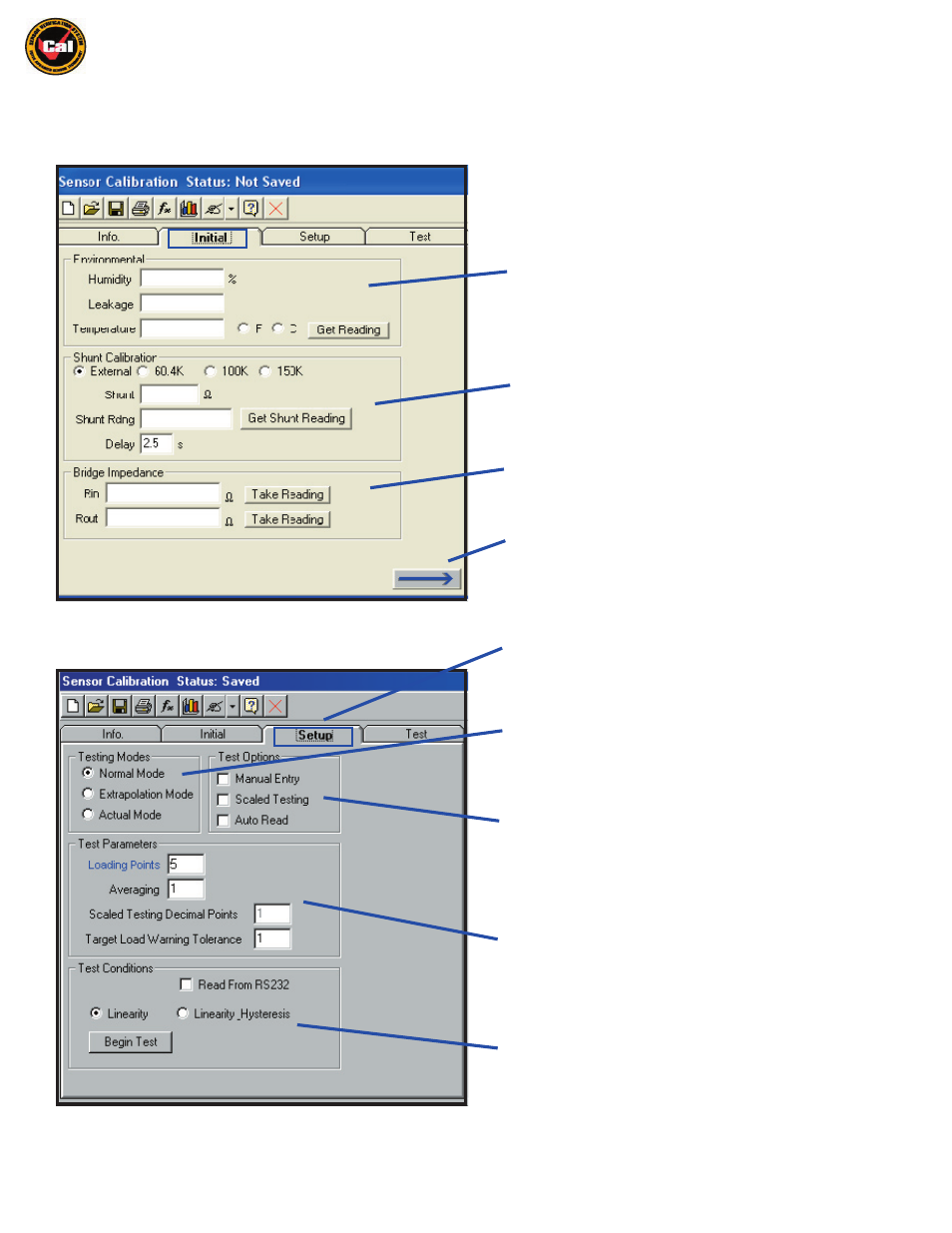
The next Tab or Window under the Information Tabs section of the Calibration / Verification interface is the
Initial Tab
, where you will do
the
Initial
setup for your test: Record Environmental conditons, perform Shunt Calibration with either the built-in Shunt values,or with your
own, external shunt resistors, and also take and record Bridge Resistance readings.
The first section of the
Initial
tab is the Environmental
Conditions section; here you can enter and record the relative
humidity levels and leakage factor for your test, as well as obtain
and record the temperature in either Fahrenheit or Celsius from
your VCal™ temperature probe.
Next is the Shunt Calibration section; here you can use VCal™’s
built in Shunt values or select External and connect your own
shunt resistors to VCal™, and obtain and record the Shunt
Calibration readings for your test.
The final section of the
Initial
tab is the Bridge Impedance
section; here you can obtain and record the bridgeresistance
for the sensor you are calibrating by clicking the Take Reading
Button
The
Next Tab
icon will move you to the next window, in this case, to
the
Setup Tab . . .
The
Setup Tab
is where you can define the Testing Mode,
your Test Options, the Test Parameters, and the Test
Conditions for your test.
Under
Testing Modes
you can choose between Normal,
Extrapolation, and Actual Modes of Testing. Descriptions
of these Modes will be given in the Calibration/Verification
Instructions section of this Manual.
(pg. 42)
Under
Test Options
you can choose between either Manual
Entry, or Scaled Testing. More detail will be given on these
options in the Calibration/Verification Instructions section of
this Manual.
(pg. 42)
Under
Test Parameters
you can define such parameters for your
test as
Loading Points
, Averaging, Decimal Points, and Target
Load Warning Tolerances. The Scaled Testing Decimal
Points textbox allows you to select output decimal points when
performing a scaled test. More details will be given on setting
these parameters in the Calibration/Verification Instructions
section of this Manual.
(pg. 43)
Under
Test Conditions
you can define whether your test is
performed with VCal™ automatically taking readings at your
pre-determined load points, or whether you wish to read your
data from an RS232 device, and also whether you wish to test for
Linearity or Linearity / Hysteresis. There is also a button for
Beginning your test.
(pg. 43)