Technical data, 2 technical data – KROHNE IFC 050 Converter EN User Manual
Page 71
TECHNICAL DATA
8
71
IFC 050
www.krohne.com
08/2013 - 4002184002 - MA IFC 050 R02 en
8.2 Technical data
INFORMATION!
•
The following data is provided for general applications. If you require data that is more
relevant to your specific application, please contact us or your local sales office.
•
Additional information (certificates, special tools, software,...) and complete product
documentation can be downloaded free of charge from the website (Download Center).
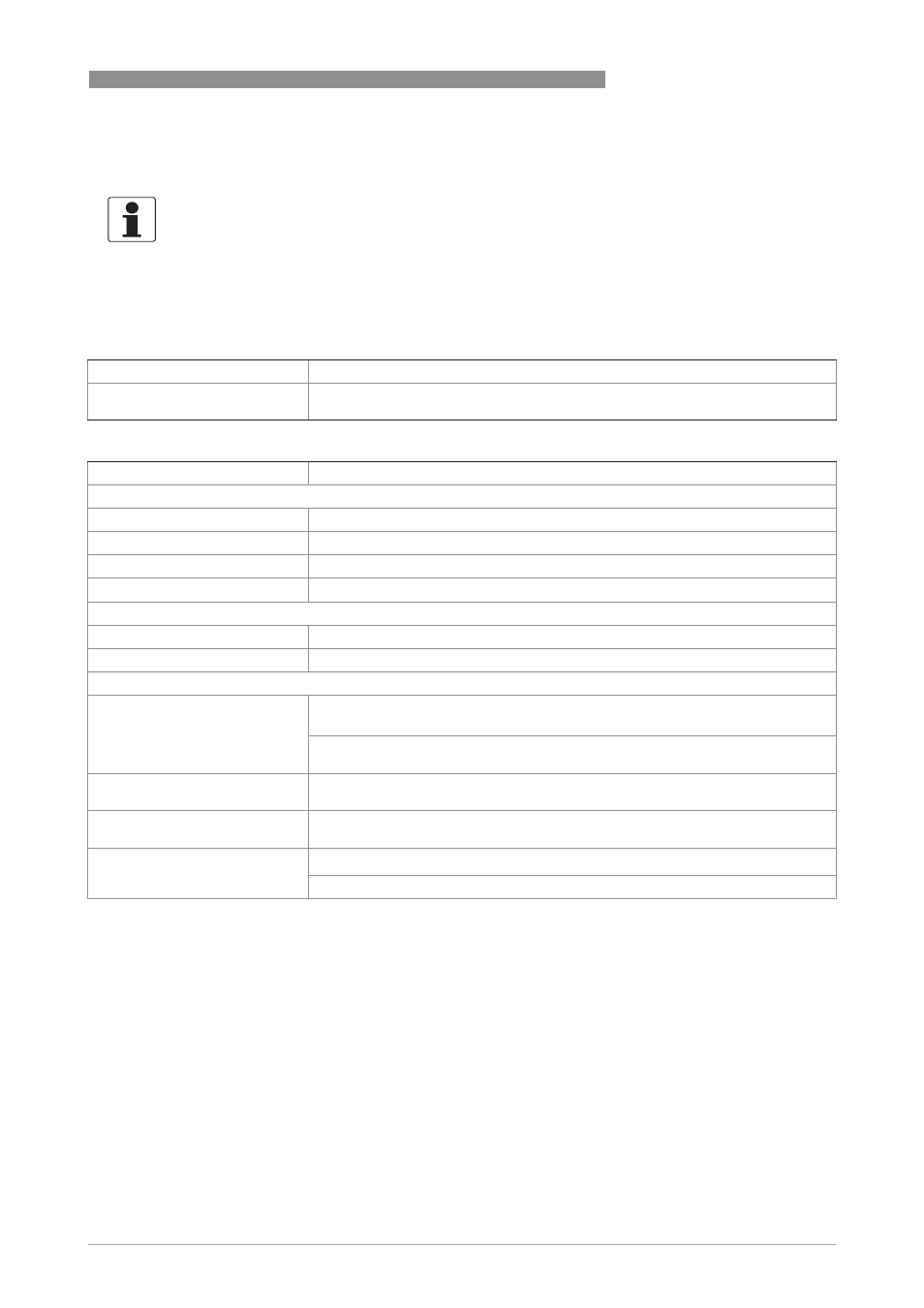
Measuring system
Measuring principle
Faraday's law of induction
Application range
Continuous measurement of current volume flow, flow velocity, conductivity, mass
flow (at constant density), coil temperature of the measuring sensor
Design
Modular construction
The measuring system consists of a measuring sensor and a signal converter.
Measuring sensor
Measuring sensor
Measuring sensor
Measuring sensor
OPTIFLUX 1000
DN10...150 / 3/8…6"
OPTIFLUX 2000
DN25...1200 / 1…48"
OPTIFLUX 6000
DN10...150 / 3/8...6"
WATERFLUX 3000
DN25...600 / 1…24"
Signal converter
Signal converter
Signal converter
Signal converter
Compact version (C)
IFC 050 C
Remote version (W)
IFC 050 W
Options
Options
Options
Options
Outputs
Current output (incl. HART
®
), pulse output, frequency output, status output and/or
limit switch
Note: It's not possible to use the pulse/frequency output with the status output at
the same time!
Counter
2 internal counters with a max. of 10 counter places (e.g. for counting volume
and/or mass units)
Verification
Integrated verification, diagnostic functions: measuring device, empty pipe
detection, stabilisation
Communication interfaces
HART
®
Modbus