Wiring, Cx2000 – Yokogawa Data Acquisition with PID Control CX2000 User Manual
Page 7
7
IM 04L31A01-02E
Wiring
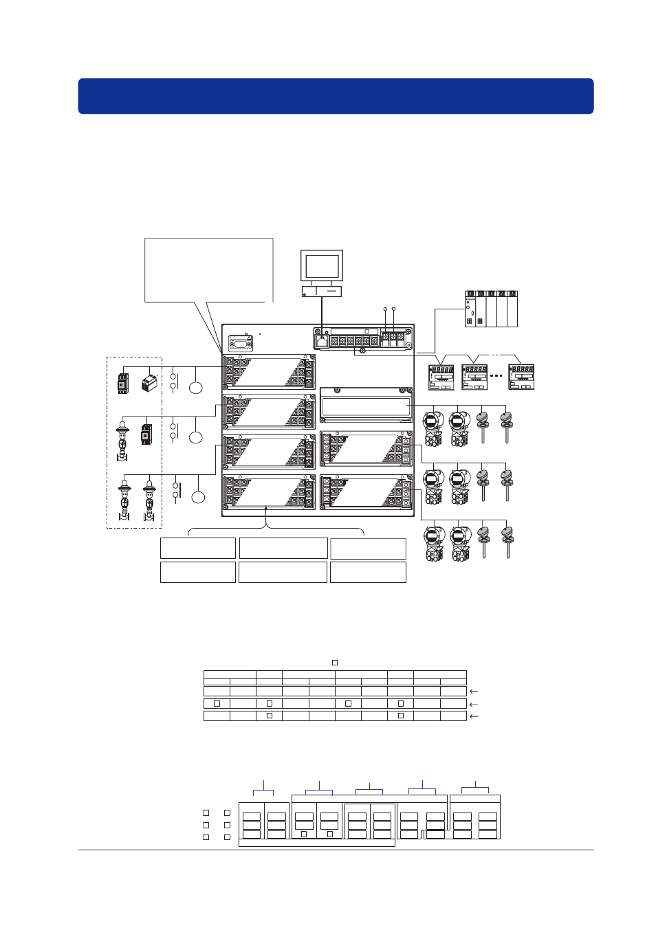
Input/Output terminals are arranged on the rear panel of the CX2000 as shown in the
figure below. The figure shows the case when option terminals are specified on the
model with 6 internal control loops and 20 measurement channels (CX2620). For the
wiring procedure of the control/measurement input/output, see chapter 2, “Installation
and Wiring” in the CX2000 User’s Manual (IM 04L31A01-01E) or the CX2000 Installation
and Connection Guide (IM 04L31A01-71E).
For a description on the connection of
communication interfaces such as the serial or Ethernet interface, see the CX2000
Communication Interface User’s Manual (IM 04L31A01-17E)
.
VIDEO OUT(VGA)
Measurement alarm
output (/A6 option)
Ethernet
Controllers (up to 16 loops)
10 universal measurement inputs
100 V to 240 VAC/
24 VDC/AC (/P1 option)
Magnet
switch
SSR
R3
R2
R1
Contact
output
6 outputs
Contact
input
6 inputs
Contact
output
6 outputs
Contact
input
6 inputs
Contact
output
6 outputs
Contact
input
6 inputs
Serial interface port
10 universal measurement inputs
10 universal measurement inputs
Option terminal
block (One
from below)
Measurement alarm output +
remote input/output
(/A6R option)
Four 24-VDC transmitter
power supplies
(/TPS4 option)
Control DIO expansion
(/CST1 option)
PLC
(such as the FA-M3
by Yokogawa)
PC
Controlling element
CX2000
Magnet
switch
Measurement alarm output +
FAIL/memory end output
(/A4F option)
Measurement alarm output +
FAIL/memory end output +
remote input/output (/A6R option)
Control output
terminal block
Loops 1 and 2
Control output
terminal block
Loops 3 and 4
Control output
terminal block
Loops 5 and 6
Analog control
input terminal block
Measurement
input terminal
block
Measurement
input terminal
block
• Universal control output: for 2 loops
Select current, voltage pulse, or
relay output
• Control contact input: 6 inputs
• Control contact output
Relay output: 2 outputs
Transistor output: 2 outputs
Terminal Arrangement of the Analog Input Terminal Block for 6 Loop Control
(Conceptual Diagram. When PV/SP computation is OFF)
The following figure denotes the three terminals (/b, +/A, -/B) of a single column using a
single cell.
LOOP1
2
1
PV
(RSP)
(RSP)
PV
PV1
PV2
LOOP2
LOOP5
LOOP6
2
1
PV
1
PV
1
PV
(RSP)
PV
PV1
PV2
LOOP3
2
1
PV
(RSP)
(RSP)
PV
PV1
PV2
LOOP4
2
1
PV
(RSP)
PV
PV1
PV2
PV, PV1, PV2: measurement input, (RSP): remote input
(not used during program control), : unused terminal
During single-loop control
During cascade control
During loop control with
PV switching
[Control mode setting]
Terminal Arrangement of Loop 1 and 2 Control Output Terminal Block(When PV/
SP computation is OFF)
LOOP1
NO
NC
C
NO
C
2
NO
NC
C
LOOP2
CTRL OUT
mA
PULS
C
LOOP2
mA
PULS
C
C
5
6
C
3
4
4
5
6
1
2
3
LOOP1
CTRL OUT
DIGITAL OUT
DIGITAL OUT
DIGITAL IN
NO
C
1
Control current/
voltage pulse
output
Contact input
Transistor
output
Relay
contact output
Control relay
contact output