Yokogawa Data Acquisition with PID Control CX2000 User Manual
Page 20
20
IM 04L31A01-02E
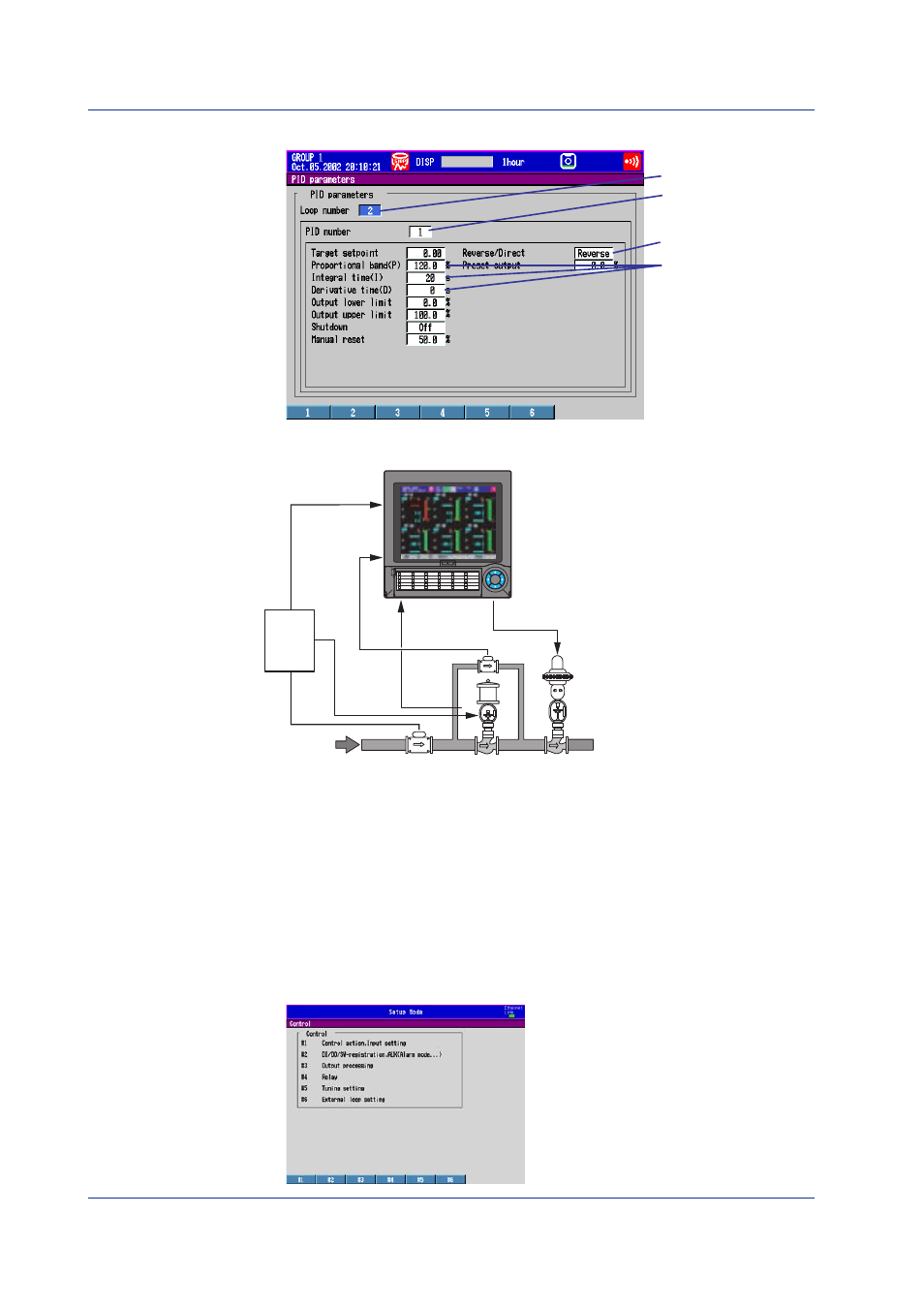
Setting PID Parameters on the Secondary Loop of Cascade Control
Select 2
Select Reverse
Select 1
Set to P=120.0% I=20 s,
D=0 s
(No need to change the
settings if the initial PID
values are set for
Press+Flow)
Control Setup Example 3: Loop Control with PV Switching
Object of Control and Description
Control valve
Switching valve
Steam
1
2
3
4
5
6
7
8
9
10
26
27
28
29
30
21
22
23
24
25
16
17
18
19
20
11
12
13
14
15
DISP
/ENTER
Distributor
+
ALM
PV1
PV2
PV switching
contact input
4 to 20mADC
current output
LOOP1 PV1
1
LOOP1 PV2
1
LOOP1 mA
2
1
Loop 1 PV input terminal
of the control input terminal block
2
Loop 1 current output terminal
of the control input terminal block
3
Relay contact output terminal
of the control output terminal block
DIGITAL IN
3
• Loop number:
1
• PID constant:
P = 120%, I = 20 s, D = 0 s
• Control direction:
Reverse
• Input type:
1-5 V for both measurement input 1 and 2
• Measurement span:
PV input 1: 0 to 300 kg/h, PV input 2: 0 to 30 kg/h
• PV range conversion:
Lower limit: 0 kg/h, Upper limit: 300 kg/h
• Flow rate setpoint:
100 kg/h
• Input switching condition: Contact input
Basic Control Settings
1.
Show the show the basic control setting menu.
See “Control Setup Example 1” for the steps to show the menu.
Examples of Control Setup Operation