Control setup example 2: cascade control – Yokogawa Data Acquisition with PID Control CX2000 User Manual
Page 15
15
IM 04L31A01-02E
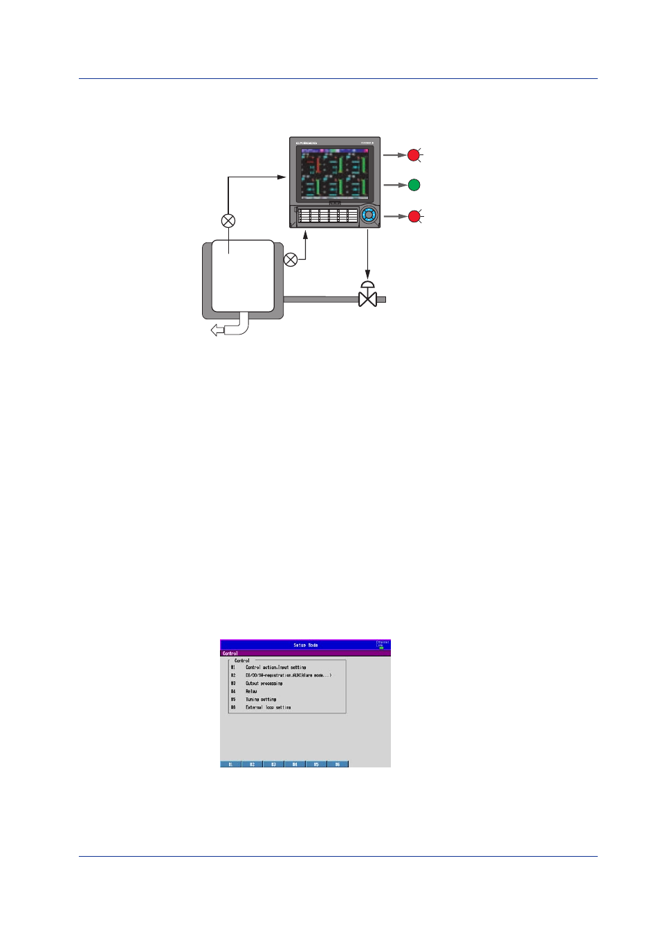
Control Setup Example 2: Cascade Control
Object of Control and Description
CX2000
High limit temperature alarm
Low limit temperature alarm
High limit steam pressure alarm
Steam
Control valve
1
2
3
4
5
6
7
8
9
10
26
27
28
29
30
21
22
23
24
25
16
17
18
19
20
11
12
13
14
15
DISP
/ENTER
DIGITAL OUT1
4
DIGITAL OUT2
4
DIGITAL OUT3
4
1
Loop 1 PV input terminal
of the control input terminal block
2
Loop 2 PV input terminal
of the control input terminal block
3
Loop 2 current output terminal
of the control input terminal block
4
Relay contact output terminal
of the control output terminal block
Pt100
Tank
Pressure
transmitter
4 to 20 mADC
current output
Primary PV input
Alarm output
LOOP1 PV
1
LOOP2 PV
2
Secondary
PV input
LOOP2 mA
3
Primary loop of cascade control
• Loop number:
1
• PID constant:
P = 20%, I = 300 s, D = 60 s
• Control direction:
Reverse
• Input type:
RTD Pt100
• Measurement span: 0 to 100°C
• Temperature setpoint: 80°C
• Alarm output:
PV high-limit alarm (high limit: 90°C), PV low-limit alarm (low
limit: 70°C)
Secondary loop of cascade control
• Loop number:
2
• PID constant:
P = 120%, I = 20 s, D = 0 s
• Control direction:
Reverse
• Input type:
1-5 V
• Measurement span: 0 to 1.00 MPa
• Output type:
Current output (4-20 mA)
• Alarm output:
PV high-limit alarm (high limit: 0.90 MPa)
Basic Control Settings
1.
Display the basic control setting menu.
See “Control Setup Example 1” for the steps to show the menu.
2.
Press the
#1 soft key
(Control action, Input setting).
3.
Press the
arrow keys
to move the cursor (blue) to the setup item box, press the
soft
key
of the value according to the following figure, and press the
DISP/ENTER key
.
Examples of Control Setup Operation