Optional function, Performance, Standard requirements for sample gas – Yokogawa IR400 User Manual
Page 98
9 - 3
IM 11G02N01-01E
3. Optional function
O
2
correction: Correction of measured NO, SO
2
and CO
gas concentrations into values at reference
O
2
concentration
Correction formula:
C = –––––––– x C
s
C
: Sample gas concentration after O
2
correction
C
s
: Measured concentration of sample
gas
O
s
: Measured O
2
concentration (Limit set-
ting: 1 to 20% O
2
, default
17%)
O
n
: Reference O
2
concentration
(value changeable by setting.0 to 19%
O
2
, default 4%)
Average value after O
2
correction and O
2
average value
calculation:
The result of O
2
correction or instanta-
neous O
2
value can be outputted as an av-
erage value in the preset period of time.
Used for averaging is the moving average
method in which sampling is carried out at
intervals of 30 seconds.
(Output is updated every 30 seconds. It is
the average value in the determined period
of time just before the latest updating.)
Averaging time is settable within 1 to 59
minutes (in increments of 1 minute) or 1 to 4
hours (in increments of 1 hour).
Average value resetting:
The above-mentioned output of average
value is started from the initial state by
opening the average value resetting input
terminals after short-circuiting for 1.5 sec-
onds or longer.
Output is reset by short-circuiting and re-
started by opening
CO concentration peak count alarm:
(added only for CO/O
2
measurement)
Alarm output turns on according to the pre-
set concentration and count.
Whenever the instantaneous value of CO
exceeds the preset concentration value,
count increments. If the count exceeds the
preset value in one hour, the alarm contacts
close.
Communication function:
RS-232C (9pins D-sub)
Half-duplex bit serial
Start-stop synchronization
ModbusTM protcol
Contents : Read/Wright parameters
Read measurement concentra-
tion and instrument status
Remark : When connecting via RS-485
interface, a RS-232C RS-
485 converter should be used.
21-O
n
21-O
s
4. Performance
Repeatability :
±
0.5% of full scale
Linearity
:
±
1% of full scale
Zero drift
:
±
1% of full scale/week
(
±
2% of full scale/week; range
between 0 to 50ppm and 0 to
200ppm)
(
±
2% of full scale/day; smaller
than 0 to 50ppm range)
Span drift
:
±
2% of full scale/week
(
±
2% of full scale/day; smaller
than 0 to 50ppm range)
Response time (for 90% FS response) :
Within 60 seconds including re-
placement time of sampling gas
(when gas flow rate is 0.5L/min)
Gas replacement time depends
on the number of measuring
components,and measuring
range
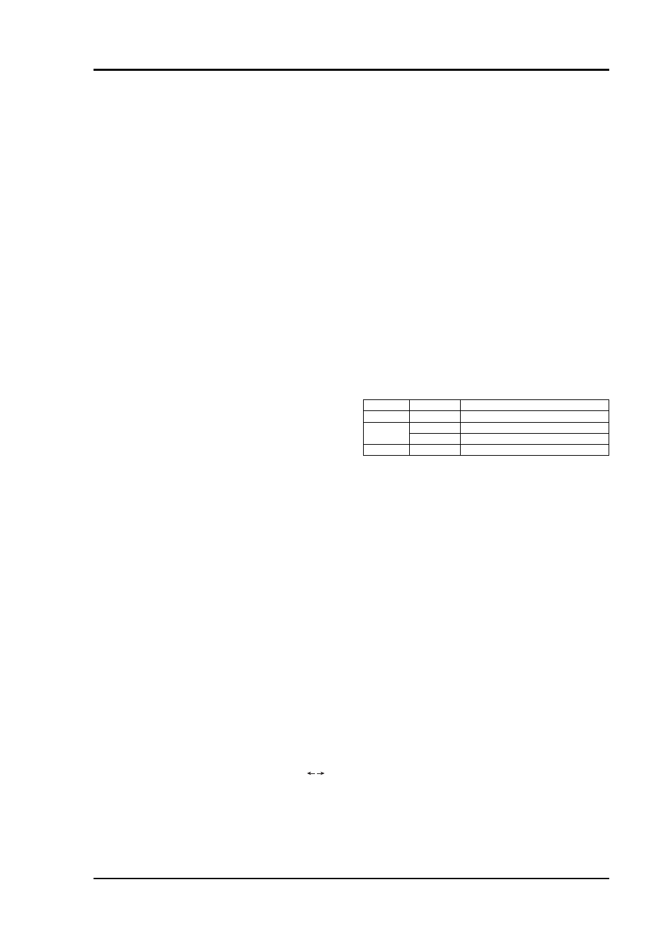
ffects of interfering gases
When sample gas contains gas components
listed below, the measurement accuracy may
suffer. Consult Yokogawa for countermeasures
or effect on accuracy.
T03s.EPS
CO
2
15% of CO
2
is equivalent to 7 to 10 ppm of CO
15% of CO
2
is equivalent to approx. 3 ppm of CH
4
Analyzer
SO
2
analyzer
CO analyzer
Interference gas
Effect
NO
2
50 ppm of NO
2
is equivalent to -6 ppm of SO
2
CH
4
analyzer
CO
2
N
2
O
1000 ppm of N
2
O is equivalent to 80 ppm of CO
5. Standard Requirements for Sample Gas
Flow rate
: 0.5
±
0.2L / min
Temperature : 0 to 50˚C
Pressure
: 10 kPa or less (Gas outlet side
should be open to the atmo-
spheric air.)
Dust
: 100
µ
g/Nm
3
in particle size of
1
µ
m or less
Mist
: Unallowable
Moisture
: Below a level where saturation
occurs at 2˚C (condensation un-
allowable).
Corrosive component: Hcl
1 ppm or less
Standard gas for calibration:
Zero gas ; Dry N
2
Span gas ; Each sample gas
having concentra-
tion 90 to 100% of its
measuring range
(recommended).
Gas beyond con-
centration 100%FS
is unusable.
In case a zirconia O
2
analyzer is
installed externally and calibra-
tion is carried out on the same
calibration gas line:
Zero gas ; Dry air or atmo-
spheric air (provided
without CO
2
sensor)