Name and description of each unit, 1 nane and description of main unit, 1 name and description of main unit – Yokogawa IR400 User Manual
Page 12
2 - 1
IM 11G02N01-01E
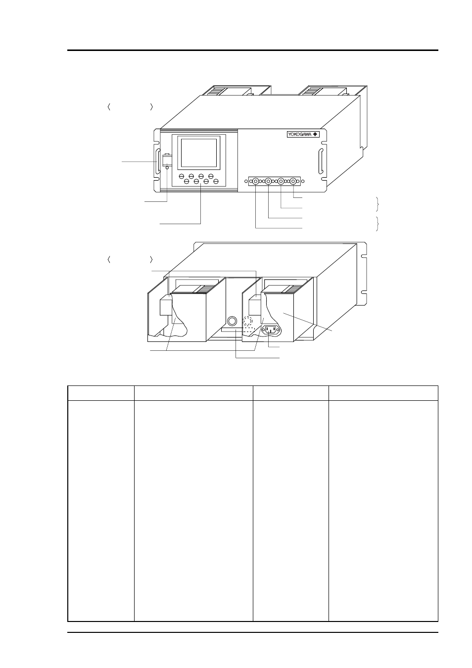
Fig. 2-1
Name
(1) Handle
(2) Power switch
(3) Display/opera-
tion
(4) Sampling gas
inlet
(5) Sampling gas
outlet
Description
Used for withdrawing the main
unit from the panel.
Used for ON/OFF the analyzer.
Liquid crysral diaplay and keys
for setting various functions
For connecting to the measuring
gas tube
Connect to the exhaust line. (A
pair of sampling gas inlet/outlet is
provided for each measuring unit.
When ordered with purge, the
piping to measuring unit 2 is built
inside. In this case, the sample gas
outlet for measuring unit 2 is used
for purge gas inlet.)
Name
(6) Sector motor
(7) Light source
cover
(8) Input/output ter-
minal connector
(9) Power inlet
(10) Protective cover
Description
For driving the rotation of
sector
Infrared light source is
arranged in the cover.
For connecting to the external
input/output terminal module
For connecting the power cable
Protective cover for the light
source and the motor. May be
removed during operation.
POWER
(1) Handle
(2) Power switch
(5) Sampling gas outlet
(4) Sampling gas inlet
(4) Sampling gas inlet
(3) Display/operation panel
For measuring
unit 1
For measuring
unit 2
(6) Sector motor
(7) Light source cover
(9) Power inlet
(5) Sampling gas outlet
(8) Input/output terminal connector
(or purge gas inlet)
Front panel
Back panel
(10) Protective cover
2. NAME AND DESCRIPTION OF EACH UNIT
2.1 Name and description of main unit