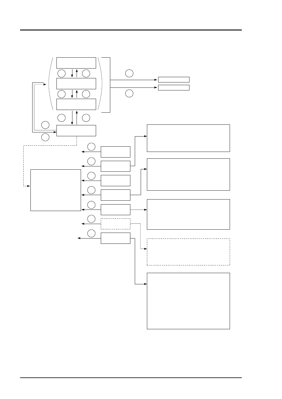
2 overview of display and operation panels, Fig. 5-2 – Yokogawa IR400 User Manual
Page 35
5 - 2
IM 11G02N01-01E
Fig. 5-2
•
Measurement mode
•
Measurement mode
•
Measurement mode
•
User mode
•
Switch Ranges
•
Calibration
Parameters
•
Alarm Setting
•
Setting of Auto
Calibration
•
Setting of
Peak Alarm
•
Parameter
Setting
* 1) The panel configuration is changed depending on the
display channel. (The measurement mode screen can
be viewed by scrolling the arrow key up and down).
* 1
* 2) The peak alarm setting is
added according to the
code symbol when CO
and O
2
components exist.
ZERO Calibration
SPAN Calibration
•
Selection of items
Start Time
Cycle
Flow Time
ON/OFF
Auto zero Calibration Run / stop
•
Setting of Auto
Zero calibration
ESC
SPAN
ZERO
MODE
ESC
MODE
ESC
ESC
ESC
ESC
ESC
ESC
ESC
ESC
ESC
MODE
MODE
•
User mode
Switch Ranges
Calibration Parameters
Alarm Setting
Setting of Auto Calibration
Setting of Auto Zero calibration
Setting of Peak Alarm
Parameter Setting
•
Selection of items
Calibration value
Zero calibration
Calibration range
Auto calibration components / range
•
Selection of items
Start Time
Cycle
Flow Time
Auto calibration ON/OFF
Auto Calibration Run / stop
•
Selection of items
Peak Alarm ON/OFF
Peak Value
Peak Count
Hysteresis
•
Selection of items
Current time
: Current time setting
Key lock
: Key lock ON/OFF
Output Hold
: ON/OFF
Reset Av. Output
: Average value
resetting
Response time
: Response time (filter)
Average Period
: Average Period
setting
Backlight Timer
: ON/OFF, timeup time
To Maintenance mode : Maintenance mode
(entry of password)
5.2 Overview of display and operation panels