Nonlinear output curve, Independent heat and cool pid, Variable time base – Watlow Series SD31 PID with Optional Countdown Timer User Manual
Page 57
The Power Limit 1and 2 (
[PL`1] and [PL`2] ) and
Output Power Scale Low 1 and 2 (
[PSL1] and [PSL2])
and Output Power Scale High 1 and 2 (
[PSH1] and
[PSH2] ) appear on the Setup Page. The calculated PID
heat and cool power values can be viewed with Power
Heat
[Po;ht] and Power Cool [Po;CL] parameters on
the Operations Page.
Nonlinear output curve
A nonlinear output curve may improve performance
when the response of the output device is nonlinear. If
Output Nonlinear Function is set to curve 1
[Cru1] or
curve 2
[Cru2], a PID calculation yields a lower actual
output level than the linear output provides. These out-
put curves are used in plastics extruder applications.
Curve 1 is for air cooled extruders and curve 2 is for wa-
ter cooled extruders.
Change the linearity for each output with Output
Nonlinear Function 1 or 2 (
[nLf1] or [nlf2] ) on the
Setup Page.
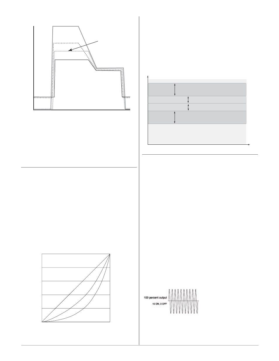
Independent Heat and Cool PID
In an application with one output assigned to heat-
ing and another assigned to cooling, each will have a
separate set of PID parameters and separate dead
bands. The heating parameters take effect when the
process temperature is lower than the set point and the
cooling parameters take effect when the process temper-
ature is higher than the set point.
Adjust heat and cool PID parameters are Operations
parameters.
Variable Time Base
Variable time base is the preferred method for con-
trolling a resistive load, providing a very short time
base for longer heater life. Unlike phase-angle firing,
variable-time-base switching does not limit the current
and voltage applied to the heater.
With variable time base outputs, the PID algorithm
calculates an output between 0 and 100%, but the out-
put is distributed in groupings of three ac line cycles.
For each group of three ac line cycles, the controller de-
cides whether the power should be on or off. There is no
fixed cycle time since the decision is made for each
group of cycles. When used in conjunction with a zero
cross (burst fire) device, such as a solid-state power con-
troller, switching is done only at the zero cross of the ac
line, which helps reduce electrical noise (RFI).
Variable time base should be used with solid-state
power controllers, such as a solid-state relay (SSR) or sili-
con controlled rectifier (SCR) power controller. Do not use
a variable time base output for controlling electromechani-
cal relays, mercury displacement relays, inductive loads or
heaters with unusual resistance characteristics.
Time
Temperature
Set Point
Heating Side Proportional Band
Heating Side Dead Band
Cooling Side Dead Band
Cooling Side Proportional Band
Actual Output P
o
w
er
0
20
40
60
80
100
PID Calculation
Linear
Curve 1
Curve 2
100
90
80
70
60
50
40
30
20
10
0
P
ercent P
o
w
er Output
Time
➔
Power Limit 100%
Power Scale Low 0%
Power Scale High 100%
Power Limit 100%
Power Scale Low 15%
Power Scale High 80%
Power Limit 70%
Power Scale Low 0%
Power Scale High 100%
Power Limit 70%
Power Scale Low 15%
Power Scale High 80%
Wa t l o w S e r i e s S D 3 1
■
5 5
■
C h a p t e r 1 0 F e a t u r e s