Watlow Series SD31 PID with Optional Countdown Timer User Manual
Page 13
Wa t l o w S e r i e s S D 3 1
■
11
■
C h a p t e r 2 I n s t a l l a n d W i r e
When choosing an EIA/TIA 232 to 485 converter, look for
one with the following features:
Two-wire capability
EIA/TIA-485 can be implemented as a two-wire sys-
tem or a four-wire system. Most Watlow controllers,
including the Series SD31, use two-wire communica-
tions when working with EIA/TIA-485. The converter
selected must have a two-wire mode. Some convert-
ers can only be used in a four-wire mode.
Automatic Send Data control
In a two-wire system, both the transmitted signals
and the received signals travel over the same pair of
wires, so the converter must have a method of chang-
ing from the transmit mode to the receive mode.
Some converters require the toggling of a control line
(usually the RTS line) to perform this transition,
while others use an automatic timing circuit. The
toggling method is dependent on the PC software to
toggle the control line and the PC’s operating system
to make that transition happen in a timely manner.
Because of these dependencies, the best choice for a
converter is one with automatic control.
Isolation
Converters are available with or without input-to-
output isolation. An isolated converter is not a re-
quirement when used with the Series SD31, but it is
recommended to avoid ground loops. Isolation could
be a consideration when the Series SD31 will be
used on a network with other devices that may re-
quire isolation.
Power Supply
Many converters can be powered up either through
the signals of a serial port or through an external
power supply. Because some computers, such as lap-
tops, do not always provide enough power to supply
the converter, we recommend using an external pow-
er supply with specifications as recommended by the
converter manufacturer. Isolated converters may re-
quire two supplies.
Biasing and termination
If the system does not work properly, it may need
termination resistors at each end of the network. A
typical installation would require a 120-ohm resistor
across the transmit/receive terminals (3 and 4) of the
last controller in the network and the converter box.
Pull-up and pull-down resistors may be needed at
the converter to maintain the correct voltage during
the idle state. The pull-up resistor is connected be-
tween the positive of the DC supply and the T+/R+
terminal. The pull-down resistor is connected be-
tween the negative of the DC supply and the T-/R-
terminal.
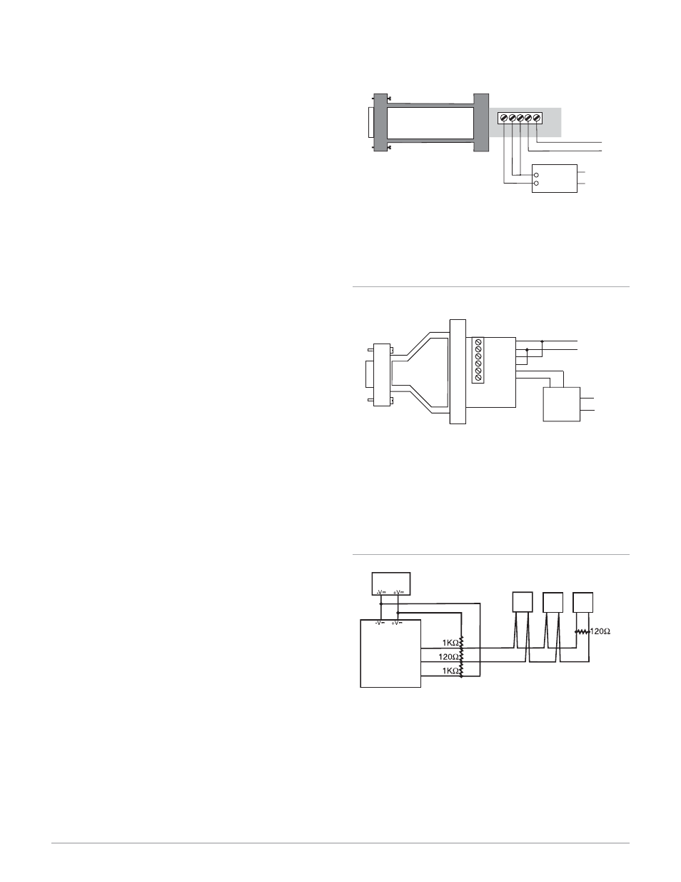
Selecting an EIA/TIA-232 to EIA/TIA-485 Converter
Figure 11a — B&B Converters
Non-Isolated Converter - 485SD9TB
B&B Electronics Manufacturing Company,
(815) 433-5100, http://www.bb-elec.com/
Figure 11b — B&B Converters
Isolated Converter - 4850I9TB
B&B Electronics Manufacturing Company,
(815) 433-5100, http://www.bb-elec.com/
Figure 11c — Wiring bias and termination resistors.
Controllers must be wired in a daisy chain configuration.
Add a 120
Ω
Ω
termination resistor on the last controller.
B
A
GND
T+/R+
T-/R-
SD
SD
SD
EIA/TIA 485
Converter
Power Supply
DC
3
3
3
4
4
4
485OI9TB
RS-232
RS-485
TD(B)
RD(A)
RD(B)
GND
+12VDC
TD(A)
+
-
120V (ac)
T-/R-
T+/R+
4
3
Watlow p/n 0830-0473-0002
Watlow p/n 0803-0473-0005
12 Volt
Power
Supply
T-/R-
TD (A)
TD (B)
T+/R+
120V
Å (ac)
Power
Supply
+
–
GND
4
3
485SD9TB
GND
12V
Î
(dc)
Watlow p/n 0830-0473-0002
Watlow p/n 0830-0473-0001
6 ft. comms cable -
Watlow p/n 0830-0473-0003