Programming page – Watlow Series SD31 PID with Optional Countdown Timer User Manual
Page 36
[hour]
/
[Po;ht]
48 R/W
[Min]
/
[A-m]
49 R/W
[`Sec]
/
[`Aut]
50 R/W
[`rdy]
/
[~CAL]
51 R/W
[Ct;SP]
/
[ht;m]
52 R/W
[Po;ht]
/
[pb;ht]
53 R/W
[`Aut]
/
[re;ht]
54 R/W
[`CAL]
/
[ra;ht]
55 R/W
[ht;M]
/
[h;hys]
56 R/W
[pb;ht]
/
[CL;m]
57 R/W
[re;ht]
/
[pb;Cl]
58 R/W
[ra;ht]
/
[re;CL]
59 R/W
[CL;m]
/
ra;Cl]
60 R/W
[pb;Cl]
/
[C;hys]
61 R/W
re;CL]
/
[A1;hi]
62 R/W
ra;Cl]
/
[A1;Lo]
63 R/W
[A1;hi]
/
[A2;hi]
64 R/W
[A1;Lo]
/
[A2;Lo]
65 R/W
[A2;hi]
/
[none]
66 R/W
[A2;Lo]
/
[none]
67 R/W
Wa t l o w S e r i e s S D 3 1
■
34
■
C h a p t e r 7 P r o g r a m m i n g
Display
Parameter Name
Description
Settings
Range
(Integer values for Modbus in paren-
theses.)
Default-
Timer ** /
Standard
Modbus*
(less 40,001
offset)
Read/Write
Appears if:
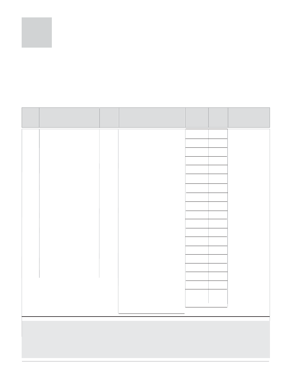
Programming Page
7
The Programming Page allows you to select what parameters appear on the Operations Page. To go to the Pro-
gramming Page, press the
ß key and Infinity ˆ keys for six seconds from the Home Page. {Prog} will appear in
the display.
•
Press the Up
¿ or Down ¯ keys to move through the parameter prompts, P1-P20.
•
To change a parameter value, press and hold the
ß key, and press the Up ¿ or Down ¯ keys to change the
value.
•
Release the
ß key and press the Up ¿ or Down ¯ keys to move through the parameter prompts, P1-P20.
•
Press the Infinity Key
ˆ at any time to return to the Home Page.
[~~P1] Parameter Location 1
[~~P2] Parameter Location 2
[~~P3] Parameter Location 3
[~~P4] Parameter Location 4
[~~P5] Parameter Location 5
[~~P6] Parameter Location 6
[~~P7] Parameter Location 7
[~~P8] Parameter Location 8
[~~P9] Parameter Location 9
[~P10] Parameter Location 10
[~P11] Parameter Location 11
[~P12] Parameter Location 12
[~P13] Parameter Location 13
[~P14] Parameter Location 14
[~P15] Parameter Location 15
[~P16] Parameter Location 16
[~P17] Parameter Location 17
[~P18] Parameter Location 18
[~P19] Parameter Location 19
[~P20] Parameter Location 20
Note: All parameter locations have the same range of possible values.
* Low register numbers contain the two higher bytes; high register numbers contain the two lower bytes of the four-byte integer.
Decimal precision is implied at three decimal places unless otherwise noted.
** Timer version only (SDXX-XXXX- XTXX)
All parameter locations
always appear on the
Programming Page.
**Only appears when
the timer option is pres-
ent. (SD31-XXXX-
XTXX)
[none] (0) None
[`CAL] (1) Calibration Offset
[`C-F] (2) Temperature Units (Setup Page)
[A1;Lo] (3) Alarm 1 Low
[A1;hi;] (4) Alarm 1 High
[A2;Lo] (5) Alarm 2 Low
[A2;hi] (6) Alarm 2 High
[hys1] (9) Alarm Hysteresis 1 (Setup Page)
[hys2] (10) Alarm Hysteresis 2 (Setup Page)
[addr] (12) Modbus Device Address (Setup
Page)
[`Aut] (13) Autotune
[A-m] (14) Auto-Manual
[Po;ht] (15) Power Heat
[Po;CL] (16) Power Cool
[ht;M] (17) Heat Control Method
[Pb;ht] (18) Prop. Band Heat
[It;ht] (19) Integral Heat OR
[re;ht] (19) Reset Heat
[dEht] (20) Derivative Heat OR
[ra;ht] (20) Rate Heat
[db;ht] (21) Dead Band Heat
[h;hys] (22) Heat Hysteresis
[CL;M] (23) Cool Control Method
[Pb;Cl] (24) Prop. Band Cool
[It;Cl] (25) Integral Cool OR
[rE;Cl] (25) Reset Cool
[dE;Cl] (26) Derivative Cool OR
[ra;Cl] (26) Rate Cool
[db;Cl] (27) Dead Band Cool
[C;hys] (28) Cool Hysteresis
[prop] (29) Proportional Term
[``It] (30) Integral Term
[``dE] (31) Derivative Term
[rP;rt] (32) Ramp Rate (Setup Page)
[hour] (33) Countdown Timer Hours*
[Min] (34) Countdown Timer Minutes*
[`Sec] (35) Countdown Timer Seconds*
[Ct;SP] (36) Closed Loop Timer Set Point*
[Ot;SP] (37) Open Loop Timer Set Point*
[`rdy] (38) Ready Band*
[CC;SP] (39) Closed Loop Control Set Point*
[OC;SP] (40) Open Loop Control Set Point*