Filter time constant, Sensor selection, Access lockout – Watlow Series SD31 PID with Optional Countdown Timer User Manual
Page 53: Set point low limit and high limit, High scale and low scale
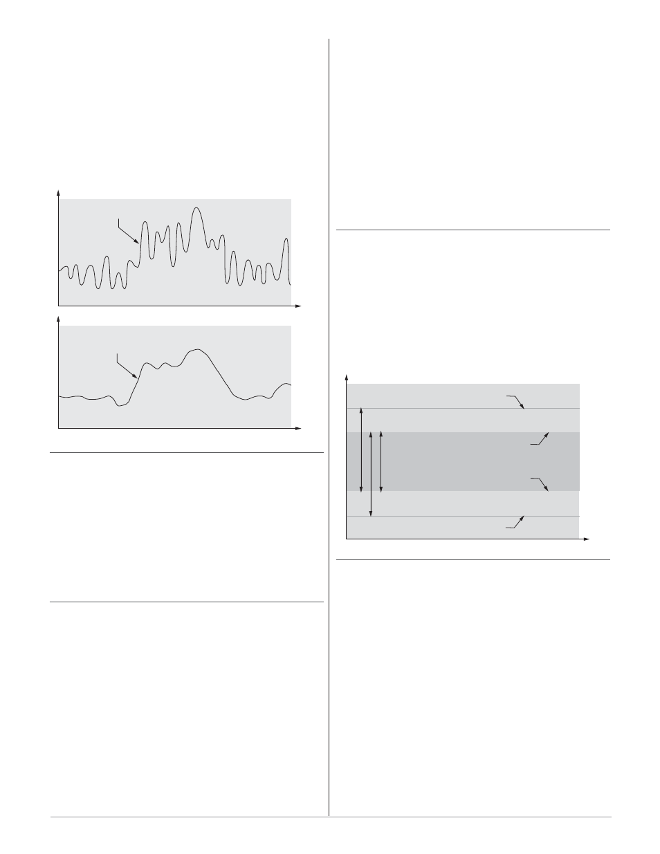
Filter Time Constant
Filtering smoothes an input signal by applying a
first-order filter time constant to the signal. The dis-
played value, the controlled value or both the displayed
and controlled values can be filtered. Filtering the dis-
played value makes it easier to monitor. Filtering the
signal may improve the performance of PID control in a
noisy or very dynamic system.
Select filter options with Input Filter
[Ftr;E]. Select
the Filter Value with
[FLtr] (Setup Page).
Sensor Selection
You need to configure the controller to match the in-
put device, which is normally a thermocouple, RTD or
process transmitter. When you select an input device,
the controller automatically sets the input linearization
to match the sensor. It also sets high and low limits,
which in turn limit the set point range-high and range-
low values.
Select the sensor type with Sensor Type
[`Sen]
(Setup Page).
Access Lockout
The user’s access to the Operations Page can be con-
trolled through the
[`loc] parameter. The [`loc] pa-
rameter appears at the end of the Setup Page. It does
not affect the Setup, Factory or Programming Pages.
[``0] All the Operations Page parameters may be
viewed or changed.
[``1] The set point, process value, auto-manual selec-
tion and alarm settings are the only visible Operations
Page parameters. Set point is adjustable in this level.
Auto-manual selection and autotune are permitted.
During manual operation, the percent power is ad-
justable.
[``2] The set point, process value, auto-manual selec-
tion and alarm settings are the only visible Operations
Page parameters. Set point is adjustable in this level.
Auto-manual selection is permitted. During manual op-
eration, percent power is adjustable.
[``3] The set point, process value and alarm settings
are the only visible Operations Page parameters. Set
point is adjustable. Auto-manual selection is not per-
mitted. During manual operation, percent power is ad-
justable.
[``4] The set point and process values are the only
visible Operations Page parameters, set point is not ad-
justable. During manual operation, percent power is not
adjustable.
Set Point Low Limit and High Limit
The controller constrains the set point to a value be-
tween a low limit and a high limit. The high limit can-
not be set higher than the sensor high limit or lower
than the low limit. The low limit cannot be set lower
than the sensor low limit or higher than the high limit.
Set the set point range with Set Point Low
[SP;Lo]
and Set Point High
[SP;hi] (Setup Page).
High Scale and Low Scale
When an analog input is selected as process voltage
or process current input, you must choose the value of
voltage or current to be the low and high ends. For ex-
ample, when using a 4 to 20 mA input, the scale low
value would be 4.00 mA and the scale high value would
be 20.00 mA. Commonly used scale ranges are: 0 to 20
mA, 4 to 20 mA, 0 to 5V, 1 to 5V and 0 to 10V.
The Series SD31 allows you to create a scale range
for special applications other than the standard ones
listed above. Reversing of the scales from high values to
low values is permitted for analog input signals that
have a reversed action. For example, 50 psi = 4 mA and
10 psi = 20 mA.
Select the high and low values with Process Scale
Low
[Sc;lo] and Process Scale High [Sc;hi] (Setup
Page).
Set Point Range (must be between Range High and Range Low)
Low Limit of selected Sensor Range
High Limit of selected Sensor Range
Temperature
Range High Range (between High Limit of Sensor and Range Low)
Range Low Range (between Low Limit of Sensor and Range High)
Range Low
Range High
Unfiltered Input Signal
Time
Te
m
p
er
ature
Filtered Input Signal
Time
Te
m
p
er
ature
Wa t l o w S e r i e s S D 3 1
■
5 1
■
C h a p t e r 1 0 F e a t u r e s