Event input 1 wiring, 11 event input 1 wiring, Digital event input 2 – Watlow Series 988 User Manual
Page 21: Digital event input 1, Figure 2.11b, Figure 2.11a, Available on all units
WATLOW Series 988 User’s Manual
2.11
Installation and Wiring, Chapter 2
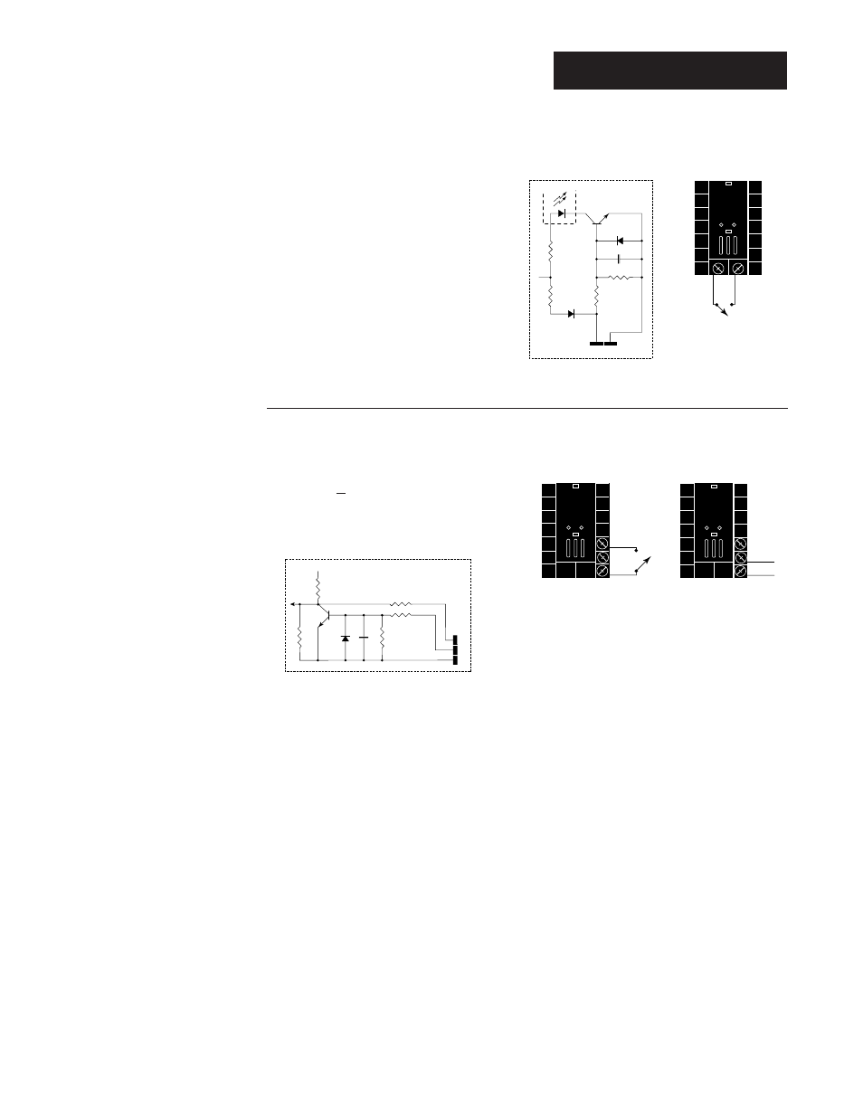
Figure 2.11b —
Digital Event Input 2
98 _ _ - _ 5 _ _ - _ _ _ _
open 0-3VÎ (dc) Event Input 2 off
closed 14-36VÎ (dc) Event Input 2 on
Figure 2.11a —
Digital Event Input 1
Available on all units.
open 14-36VÎ (dc) Event Input 1 off
closed 0-3VÎ (dc) Event Input 1 on
20
18
+5VÎ (VDC)
100
Ω
750
Ω
4.7K
Ω
1K
Ω
.01
µf
19
Internal Circuitry
23
24
+
-
24
23
+24VÎ (dc)
10K
Ω
4.99K
Ω
OPTO
ISOLATOR
750
Ω
.01
µf
4.99K
Ω
Internal Circuitry
20
18
20
19
+
-
NOTE:
Successful installa-
tion requires five
steps:
• Model number and
software choice
(Appendix);
• DIP switch set-
tings (Chapter 1);
• Sensor match
(Chapter 2 and
Appendix);
• Sensor installation
(Chapter 2); and
• Wiring (Chapter 2).
Event Input 1 Wiring
See also other documents in the category Watlow Sensors:
- 12LS Controller (111 pages)
- 8LS Controller (140 pages)
- 8PID Controller (55 pages)
- Addendum to EZwarePlus (50 pages)
- ANASCAN (62 pages)
- ANASOFT (95 pages)
- ANAWIN 2 (154 pages)
- ANAWIN 3 (23 pages)
- Calibrating Watlow Series 988 Family Process Controls (19 pages)
- CAS (98 pages)
- CAS200 (124 pages)
- CLS (180 pages)
- CLS200 (251 pages)
- CLS200, MLS300 and CAS200 (92 pages)
- Control Console (12 pages)
- CPC400 (230 pages)
- DIN-A-MITE Style A (9 pages)
- DIN-A-MITE Style B (14 pages)
- DIN-A-MITE Style C (22 pages)
- DIN-A-MITE Style D (9 pages)
- DIN-Mount Adapter Instruction Sheet, Rev A (1 page)
- Dual DAC (4 pages)
- EM Gateway (28 pages)
- E-Safe Hybrid Relay Rev B (4 pages)
- E-SAFE II Hybrid Power Switch (4 pages)
- EZwarePlus Programming (264 pages)
- EZ-ZONE PM (111 pages)
- EZ-ZONE PM PID (125 pages)
- EZ-ZONE PM Express Limit (34 pages)
- EZ-ZONE PM Express (35 pages)
- EZ-ZONE PM Integrated Controller (181 pages)
- EZ-ZONE RM Limit Module Rev C (127 pages)
- EZ-ZONE RMA Modul (79 pages)
- EZ-ZONE RMC (236 pages)
- EZ-ZONE RME (124 pages)
- EZ-ZONE RMH (161 pages)
- EZ-ZONE RUI/Gateway (62 pages)
- EZ-ZONE RM-Scanner-Modul (140 pages)
- EZ-ZONE ST (97 pages)
- F4 External Event Board - Rev.B (2 pages)
- HG Series Mercury Displacement Relay (6 pages)
- LogicPro (296 pages)
- Mercury Relay or MDR Retrofit (13 pages)
- MICRODIN (24 pages)
- MICRODIN (106 pages)