Setup steps, Indicator lights, Over view – Watlow MICRODIN User Manual
Page 9
Over
view
Setup Steps
1. Set up communications.
2. Set the controller’s address and baud speed with the DIP switches on the top
, Communications Setup). The controller uses eight data
bits with no parity.
, Wiring).
, Wiring).
5. Communicate with MicroDIN via an EIA-485 network with Modbus
™
RTU protocol.
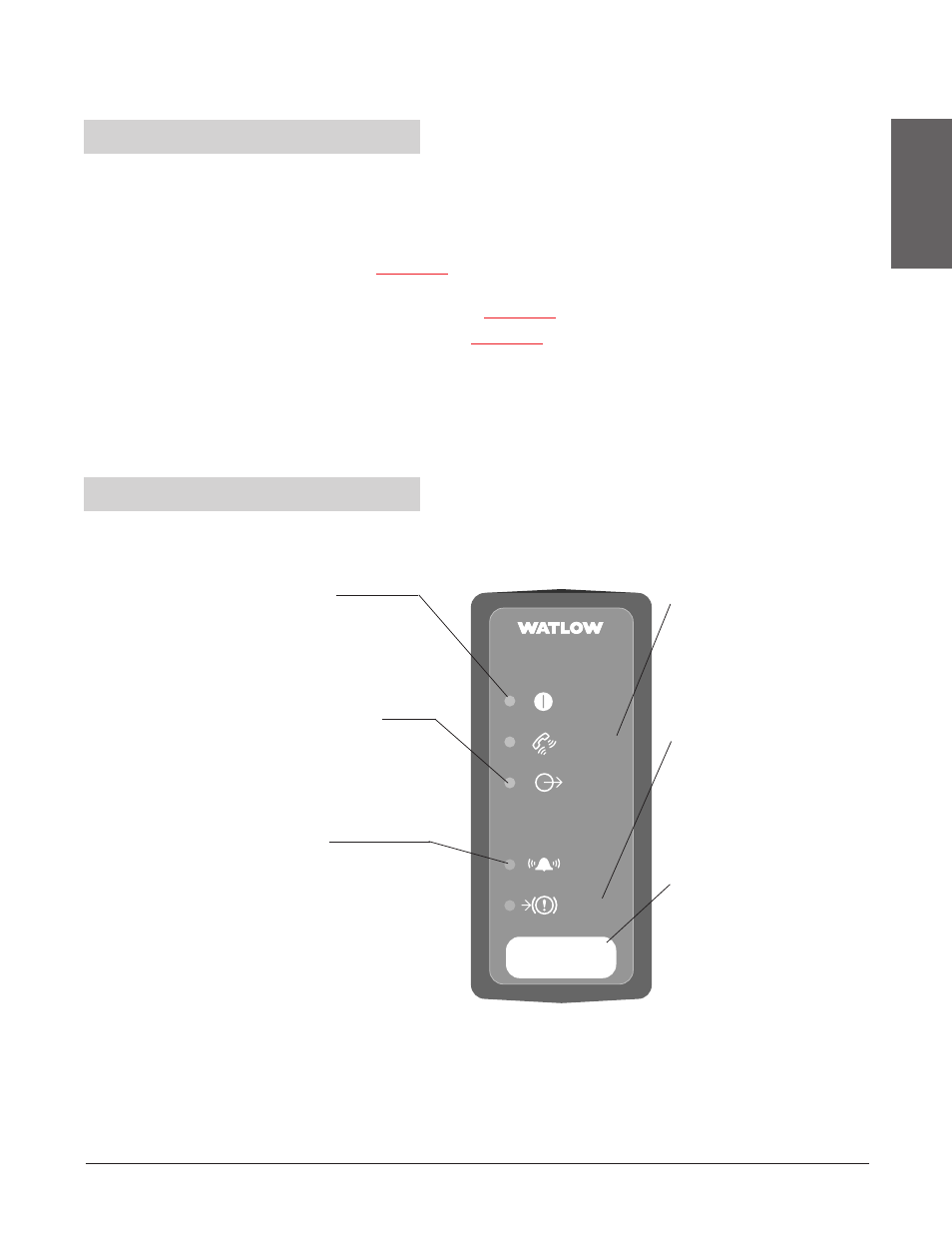
Communications
Green Light pulsates when the
controller sends or receives
valid data over its network port.
• If it does not light up, check
the controller address and the
communications setup.
Input Error
Red Light is lit if there is a
sensor problem. If it is lit:
• Verify the sensor wiring,
polarity and function.
• Rewire or replace as
necessary.
Address Field
Record the unit’s address in
erasable marker here.
Address
Power
Comms
Alarm
Temperature Controller
MicroDIN
Temperature Controller
MicroDIN
Control
Output
Input
Error
Figure 1.3 - MicroDIN
indicator lights
Indicator Lights
Power
Green light stays
lit when the power is on
and the controller is ok.
• If it isn’t on or pulsates,
check your power source.
Control Output
Green light is lit or flashes
when the control output is
energized.
• If it does not light up, the
output is not turning on.
Alarm
Red Light is lit during an
input alarm condition.
If it is lit:
• Correct alarm condition
or change alarm
configuration.
• Reset the alarm if it is
latched.
Wa t l o w M i c r o D I N 1 . 3