Microdin rj-11 and 10-pin connectors, Install and wire – Watlow MICRODIN User Manual
Page 25
Wa t l o w M i c r o D I N 3 . 5
Install and Wire
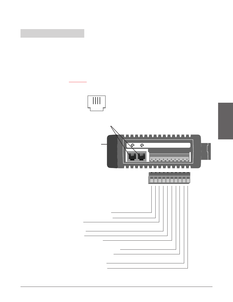
MicroDIN RJ-11 and 10-pin Connectors
The MicroDIN 10-pin screw terminal connector, on the bottom of the case, links
it to its power supply, control input, control output and alarm output. Use 26- to
14-gauge wire to connect to the plug terminals.
The alarm output is an electromechanical relay.
See the Appendix for information on sensor ranges and specifications. See
: Parameters for information about software configuration.
1
2
3
4
5
6
7
8
9
10
Input
1. S1 or thermocouple+
2. S3 or thermocouple-
3. S2
Control Output
4. dc+
5. dc-
6. common (COM)
Alarm Output (electromechanical relay)
7. alarm normally open (NO)
8. alarm common (COM)
Power
9. L2, 24V‡ (ac/dc)-
10. L1, 24V‡ (ac/dc)+
Figure 3.5 - Bottom view
of MicroDIN case with
connector assignments.
communications
sockets 1 and 2
(RJ-11)
1 2 3 4 5 6 7 8 9 10
10-pin removable connector
Front of Unit
Ó
WARNING:
To avoid potential
electric shock, use
National Electric Code
(NEC) safety practices
when wiring and
connecting this unit to a
power source and to
electrical sensors or
peripheral devices.
Failure to do so could
result in injury or death.
ç
WARNING:
Install high or low
temperature limit control
protection in systems
where an over
temperature fault
condition could present a
fire hazard or other
hazard. Failure to install
temperature limit control
protection where a
potential hazard exists
could result in damage to
equipment and property
and injury to personnel.
Bottom View
A B C D