Output and power wiring, Install and wire – Watlow MICRODIN User Manual
Page 27
Wa t l o w M i c r o D I N 3 . 7
Install and Wire
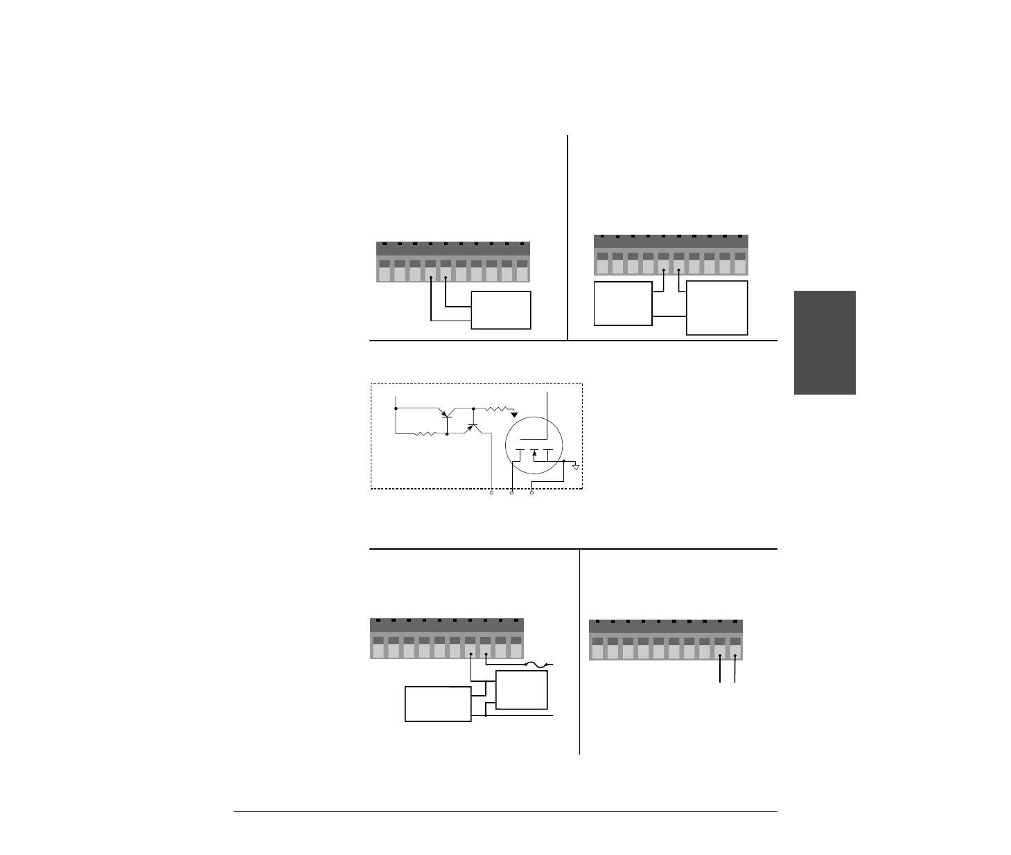
Output and Power Wiring
1 2 3 4 5 6 7 8 9 10
+
External
Load
-
dc+
COM
dc-
+
-
Power
Supply
60V max.
1A max.
1 2 3 4 5 6 7 8 9 10
External
Load
COM
N.O.
Relay
Suppression
Fuse
L1
L2
NOTE:
The current limit feature
is disabled in this version
of the controller.
NOTE:
Relay suppression
required only for
inductive loads.
+24V
Î
(dc)
Internal Circuitry
20
Ω
2K
Ω
4
dc+
5
dc-
6
COM
10
1 2 3 4 5 6 7 8 9
24V
‡
(ac/dc)
- +
Figure 3.7c — Internal Output Circuitry
Figure 3.7d — Alarm Output
Figure 3.7b —
Control Output, Open Collector
with External Power Supply
Figure 3.7e — Power Wiring
Ó
WARNING:
To avoid potential
electric shock, use
National Electric Code
(NEC) safety practices
when wiring and
connecting this unit to a
power source and to
electrical sensors or
peripheral devices.
Failure to do so could
result in injury or death.
1 2 3 4 5 6 7 8 9 10
+
External
Load
-
dc+
COM
dc-
Figure 3.7a —
Control Output, Switched DC
with Internal Power Supply
External
Switching
Device
External
Switching
Device
- 12LS Controller (111 pages)
- 8LS Controller (140 pages)
- 8PID Controller (55 pages)
- Addendum to EZwarePlus (50 pages)
- ANASCAN (62 pages)
- ANASOFT (95 pages)
- ANAWIN 2 (154 pages)
- ANAWIN 3 (23 pages)
- Calibrating Watlow Series 988 Family Process Controls (19 pages)
- CAS (98 pages)
- CAS200 (124 pages)
- CLS (180 pages)
- CLS200 (251 pages)
- CLS200, MLS300 and CAS200 (92 pages)
- Control Console (12 pages)
- CPC400 (230 pages)
- DIN-A-MITE Style A (9 pages)
- DIN-A-MITE Style B (14 pages)
- DIN-A-MITE Style C (22 pages)
- DIN-A-MITE Style D (9 pages)
- DIN-Mount Adapter Instruction Sheet, Rev A (1 page)
- Dual DAC (4 pages)
- EM Gateway (28 pages)
- E-Safe Hybrid Relay Rev B (4 pages)
- E-SAFE II Hybrid Power Switch (4 pages)
- EZwarePlus Programming (264 pages)
- EZ-ZONE PM (111 pages)
- EZ-ZONE PM PID (125 pages)
- EZ-ZONE PM Express Limit (34 pages)
- EZ-ZONE PM Express (35 pages)
- EZ-ZONE PM Integrated Controller (181 pages)
- EZ-ZONE RM Limit Module Rev C (127 pages)
- EZ-ZONE RMA Modul (79 pages)
- EZ-ZONE RMC (236 pages)
- EZ-ZONE RME (124 pages)
- EZ-ZONE RMH (161 pages)
- EZ-ZONE RUI/Gateway (62 pages)
- EZ-ZONE RM-Scanner-Modul (140 pages)
- EZ-ZONE ST (97 pages)
- F4 External Event Board - Rev.B (2 pages)
- HG Series Mercury Displacement Relay (6 pages)
- LogicPro (296 pages)
- Mercury Relay or MDR Retrofit (13 pages)
- MICRODIN (24 pages)