Calibrating microdin, For the, See p. 6.6 – Watlow MICRODIN User Manual
Page 86: Operations, Thermocouple input procedure, Rtd input procedure, Equipment required, Setup and calibration
6 . 6 Wa t l o w M i c r o D I N
Operations
Note: For information on writing Modbus
™
RTU
communications software for MicroDIN, see the
Appendix.
To enter the calibration mode, first enter the
diagnostics mode; send value 1789 to register
1512. Once in Diagnostics mode, to enter
calibration mode, send 1415 to register 1600.
To restore factory calibrations settings, send value 1
to register 1601.
Thermocouple Input Procedure
Equipment Required
• Type J reference compensator with reference
junction at 32°F/ 0°C, or type J thermocouple
calibrator set at 32°F / 0°C.
• Precision millivolt source, 0-50mV minimum range,
0.002mV resolution.
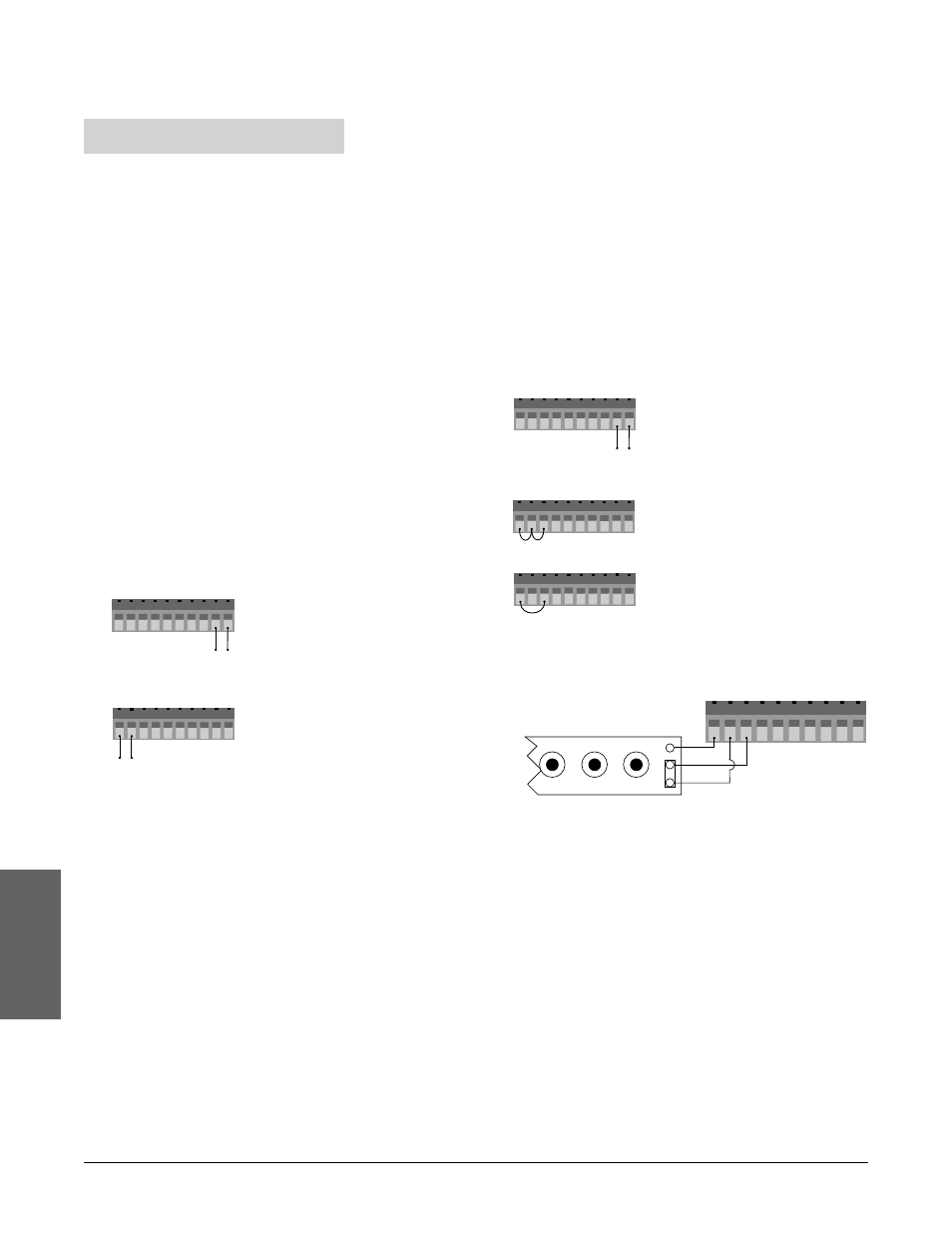
Setup and calibration
1) Connect voltage to MicroDIN Terminals 9, 10.
2) Connect the millivolt source to Terminal #1 (+) and
Terminal #2 (-) on the MicroDIN with copper wire.
3) Enter 0.000mV from the millivolt source to the
MicroDIN. Allow at least 10 seconds to stabilize.
• Send value 1 to register 1603 to store 0.000mV
input.
4) Enter 50.000mV from the millivolt source to the
MicroDIN. Allow at least 10 seconds to stabilize.
• Send value 2 to register 1603 to store 50.000mV
input.
5) Disconnect the millivolt source and connect the
reference compensator or T/C calibrator to terminal
#1 (+) and Terminal #2 (-).With Type J t/c wire, if
using a compensator, turn it on and short the input
wires. When using a Type J calibrator, set it to
simulate 32°F / 0°C. Allow 10 seconds for the
control to stabilize.
• Send register 1603 value 3 to store CJC input
(32°F, type J, compensated).
6) Rewire for operation and verify calibration.
RTD Input Procedure
Equipment Required
• 1K
Ω
precision decade box with 0.01
Ω
resolution
• Precision current source, 0-4mA range with
0.01mA resolution
Setup and calibration
1) Connect voltage to terminals #9, #10.
2) Short terminals 1, 2 and 3 together with less than 0.1
Ω
.
• Send register 1603 value 4 to store ground input.
3) Short terminals 1 and 3 together with less than 0.5
Ω
.
• Send register 1603 value 5 to store RTD lead
resistance.
4) Connect the decade box to terminals #1, #2 and #3
on the MicroDIN. Use 20 to 24 gauge copper wire.
5) Enter 15.00
Ω
from the decade box to the MicroDIN.
Allow at least 10 seconds to stabilize.
• Send value 6 to register 1603 to store 15.00
Ω
.
6) Enter 380.00
Ω
from the decade box to the
MicroDIN. Allow at least 10 seconds to stabilize.
• Send register 1603 value 7 to store 380.00
Ω
.
7) Disconnect the decade box, and connect the current
source to Terminals #2 (-) and #3 (+).
8) Enter 4.00mA from the current source to the
MicroDIN. Allow at least 10 seconds to stabilize.
• Send value 10 to register 1603 to store 4mA input.
9) Rewire for operation and verify calibration.
10
1 2 3 4 5 6 7 8 9
24V
‡
(ac/dc)
- +
10
1 2 3 4 5 6 7 8 9
24V
‡
(ac/dc)
- +
10
1 2 3 4 5 6 7 8 9
10
1 2 3 4 5 6 7 8 9
H
L
G
S1
S3
S2
Ω
General Radio Model #1433-T
10
1 2 3 4 5 6 7 8 9
10
1 2 3 4 5 6 7 8 9
-
+
Calibrating MicroDIN