Required parameters, Required parameters setup order, Communication setup – Watlow MICRODIN User Manual
Page 18: Changing this, Affects this, Document your settings below
Communication
Setup
Note: This table also appears
Wa t l o w M i c r o D I N 2 . 8
Units Type
C or F
Input Error Action
Control Output Function
Set Fixed Manual Output
O
Open Loop Detect
Sensor Type
Input Type
O
Range Low
C
D D
C
Range High
C
D D
C
Decimal Point
D D
Calibration Offset
C
D D
C
Filter Time Constant
D D
Error Clearing Mode
Power Limit Set Point
C
D D
C
High Side Power
O
Low Side Power
O
Alarm Output Function
Alarm Type
D D
Alarm Hysteresis
C
D D
C
Alarm Latching Mode
Alarm Silencing Mode
Alarm Active Sides
Alarm Logic
Alarm High
C
D D
O
C
Alarm Low
C
D D
O
C
Propband
C
D D
C
Integral
O
Reset
O
Derivative
Rate
Cycle Time
Output Hysteresis
C
D D
C
Operation Mode
Set Point
Manual Output Power
O
O O
O
Set Point
C
D D O O
C
Units T
ype
C or F Control Output Function
Sensor T
ype
Input T
ype
Range LowRange HighHigh Side Power
Low Side Power
Alarm T
ype
Operation Mode
Decimal
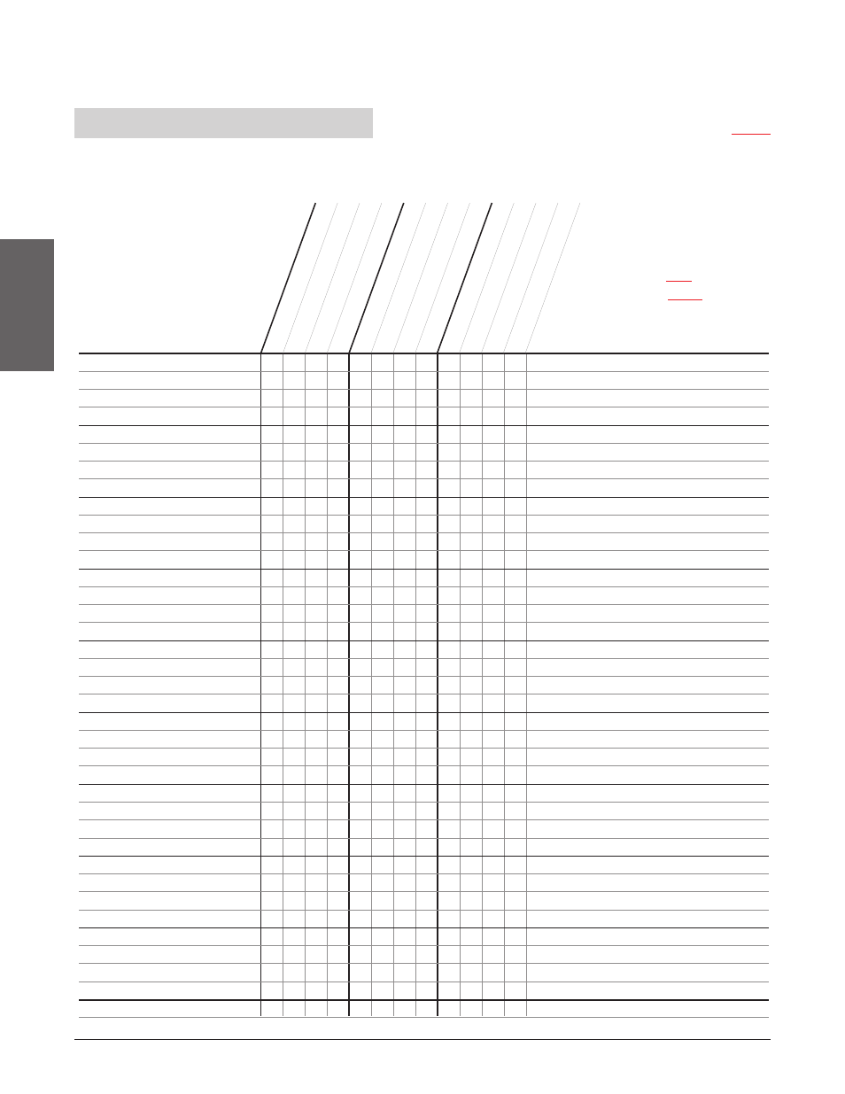
Table 2.8 - Parameters Setup order.
Changing this
➝
Affects this
➝
Document your settings below
➝
Required Parameters Setup Order
This table provides 1) the correct order of entry, 2) the effect of a parameter change, and 3) a place to document settings.
Key:
D = Changing will change the default
C = Changing will convert the
temperature scale
ç
CAUTION:
Parameters
should be set
up in this order.