Serial data format, Microdin installation wiring tasks, Communications software watlink – Watlow MICRODIN User Manual
Page 19: Other software, Communications setup
Serial Data Format
Configure your computer’s COM1 or COM2 (communications) port data format
to match the MicroDIN’s settings in the table below.
MicroDIN Installation Wiring Tasks
MicroDIN requires these wiring tasks for a successful installation
1.
Wire MicroDIN sensor input.
2.
Wire MicroDIN Output 1, the control output.
3.
Wire MicroDIN Output 2, the alarm output.
4.
Wire MicroDIN power.
5.
Connect the MicroDIN communications daisy chain.
6.
Wire the 232-to-485 converter; connect to the computer.
7.
If necessary, wire the termination and pull-up/pull-down resistors.
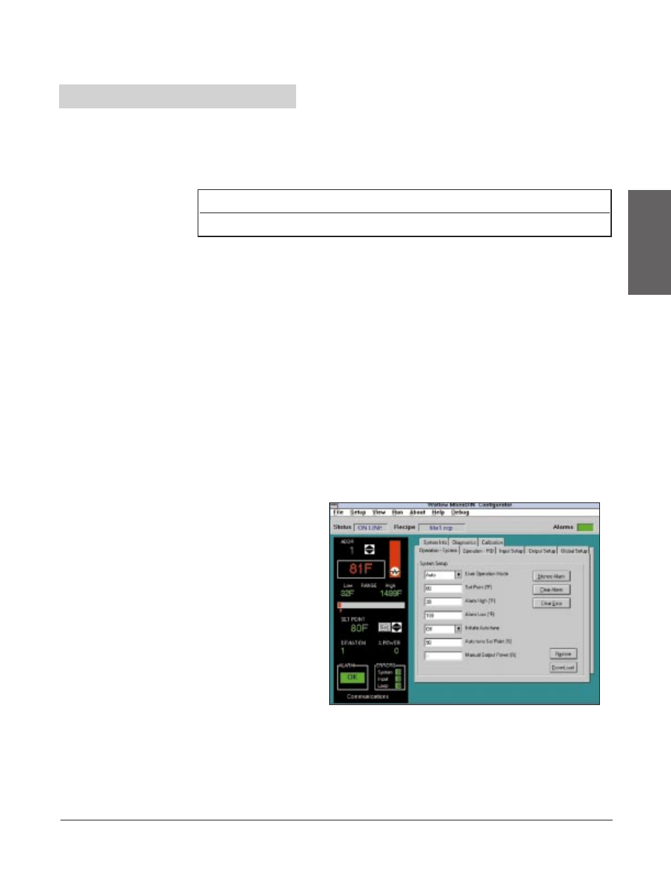
Communications Software
WatLink
Watlow offers a Modbus
™
package in WatLink,
software that will set up
and run multiple
MicroDINs over an EIA-
485 network. WatLink,
a Windows 3.31 or
Windows 95 application,
is available from any
Watlow sales rep-
resentative or authorized
distributor. WatLink can
handle up to 32 different
MicroDIN units.
Other Software
To communicate with
MicroDIN, you must use a Modbus
™
RTU (remote terminal unit) compatible
software package. Sending ASCII commands via a standard serial
communication application will not work. Refer to the Appendix if you’re writing
your own Modbus
™
RTU application.
Wa t l o w M i c r o D I N 2 . 9
Communications
Setup
Table 2.9a -
Serial Data Format
Data Bits
Parity
Stop Bit
Start Bit
8
None 1
1
Figure 2.9b -
WatLink for MicroDIN
sample software screen