2 pci board installation, 2 pci board installation -15 – Proface APL3000B - Node Box PC User Manual
Page 52
Chapter 3 Hardware Installation
3-15
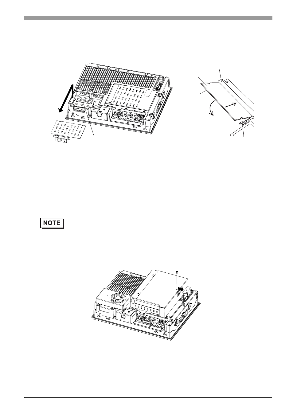
(3)
Install the main memory where the following figure shows. Insert the DIM module, which is an optional
product, into the connector completely in an oblique direction, then press it downward until it is locked
into the stopper.
(4)
Place back the Memory slot cover and fix with two screws. The torque required to tighten these screws
is 0.5 to 0.6N•m.
3.3.2
PCI Board Installation
A PCI board, which is sold on the market, can be installed on PS-3650A.
(1)
Turn OFF the power switch of the PS-A and remove the power cable. Place the PS-A on a flat, level sur-
face facing the display face downwards
(2)
Unscrew a screw of the expansion board support and remove the expansion board support.
•
The maximum size allowed for a PCI board is 174.63mm [6.88in.] × 106.68mm [4.2in.].
1
2
Connector
Stopper
Main Memory
Main Memory (DIM Module)