3 grounding, 4 i/o signal line placement, 3 grounding -12 – Proface APL3000B - Node Box PC User Manual
Page 49: 4 i/o signal line placement -12
PS-3650A / PS-3651A User Manual
3-12
3.2.3
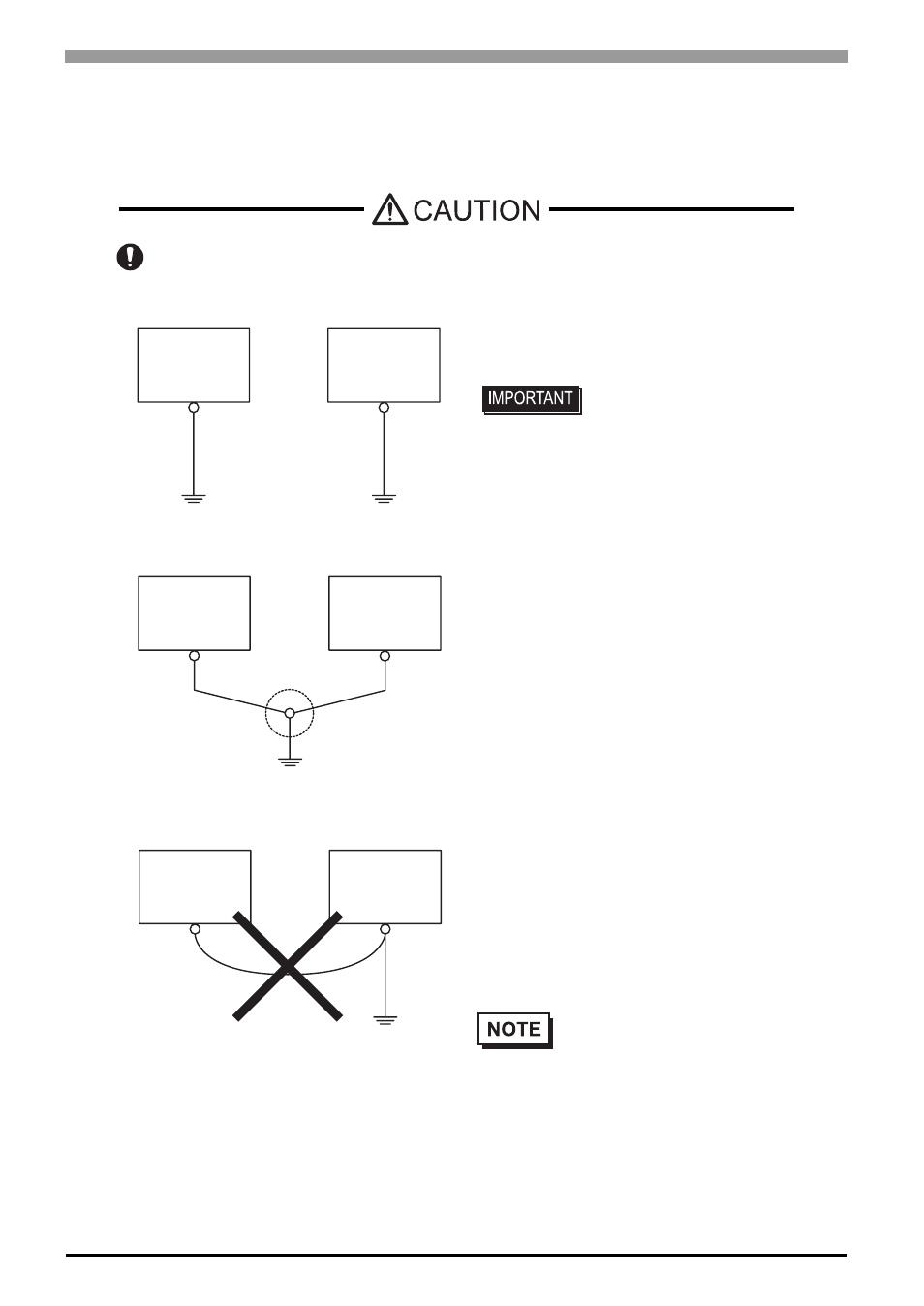
Grounding
This section describes the precautions for grounding the PS-A unit.
• When supplying power to the PS-A unit, be sure to
separate the input/output and power lines, as shown.
[diagram (a)]
• If exclusive grounding is not possible, use a common
connection point. [diagram (b)]
3.2.4
I/O Signal Line Placement
•
Input and output signal lines must be separated from the power control cables for operating circuits.
•
If this is not possible, use a shielded cable and ground the edge of the shield.
Do not use common grounding, since it can lead to an accident or machine breakdown.
• Check that the grounding
resistance is 100
Ω or less.
• FG and SG terminals are
internally connected in the PS-A.
When connecting an external
device to the PS-A using the SG
terminal, be sure to check that
no short-circuit loop is created
when you setup the system.
• The grounding wire should have
a cross sectional area of 2mm
2
or greater. Create the connection
point as close to the PS-A unit as
possible, and make the wire as
short, as possible. When using a
long grounding wire, replace the
thin wire with a thicker wire, and
place it in a duct.
•
If the equipment does not function
properly when grounded, disconnect
the ground wire from the FG terminal.
(a) Exclusive Grounding (BEST)
(b) Common Grounding (OK)
(c)Common Grounding (Not OK)
PS-A Unit
Other
Equipment
PS-A Unit
Other
Equipment
PS-A Unit
Other
Equipment