2 ras interface, 2 ras interface -9 – Proface APL3000B - Node Box PC User Manual
Page 32
Chapter 2 Specifications
2-9
2.3.2
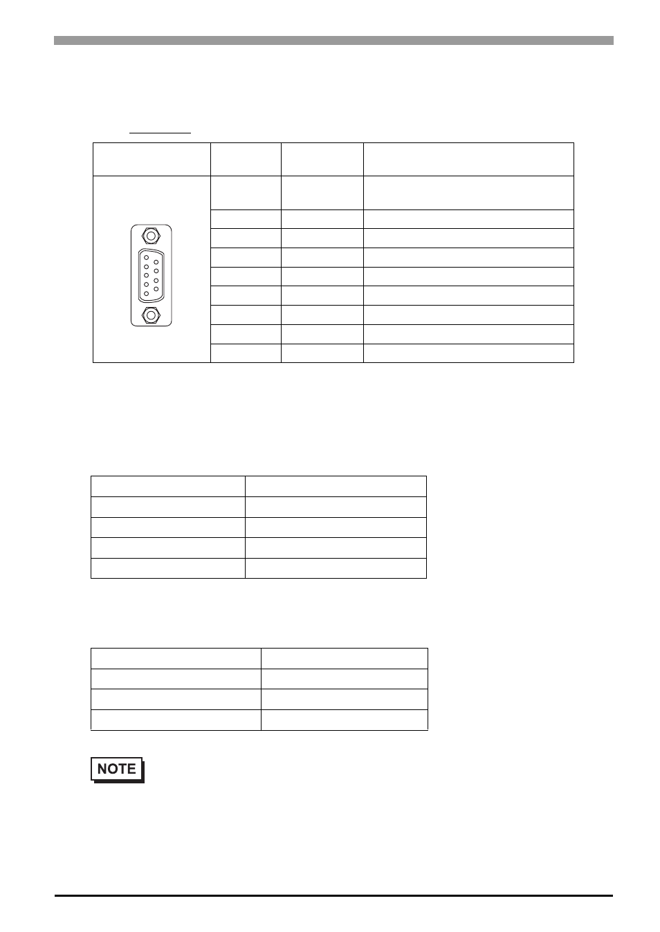
RAS Interface
Types of sockets for D-sub 9 pins are listed below.
Use #4-40 (UNC) fixing clamps to fix the joint of the interspace.
General Input (DIN 0, 1)
General Output (DOUT 0, 1)
Pin
Arrangement
Pin No.
Signal Name
Meaning
1
+12V
Output Current:100mA or less
Output Voltage: DC12V±5%
2
DOUT 0 (+)
Data Output 0(+)
3
DOUT 1 (+)
Data Output 1(+)
4
DIN 0(+)
Data Input 0 (+)
5
DIN 1(+)
Data Input 1 (+)
*1
*1 DIN1(+) can be used as Remote Reset Input of RAS feature. The factory setting is Gen-
eral Purpose Signal Input.
6
GND
SG (same as FG)
7
DOUT 0 (-)
Data Output 0 (-)
8
DOUT 1 (-)
Data Output 1 (-)
9
DINCOM
DIN GND Common
INPUT VOLTAGE RANGE
DC12V to 24V
INPUT CURRENT
Below 10mA
INNER RESISTOR
3.6K
Ω
INSULATION VOLTAGE
AC500V or more
INSULATION
Photocoupler
OUTPUT VOLTAGE RANGE
DC24V
OUTPUT CURRENT
Below 120mA
INSULATION VOLTAGE
AC500V or more
INSULATION
Photocoupler
•
For the circuit diagram, refer to "6.1.1 RAS Features".
9
6
5
1