4 part names and functions, 4 part names and functions -6, Part names and functions – Proface APL3000B - Node Box PC User Manual
Page 21: 6 1.4 part names and functions
PS-3650A / PS-3651A User Manual
1-6
1.4
Part Names and Functions
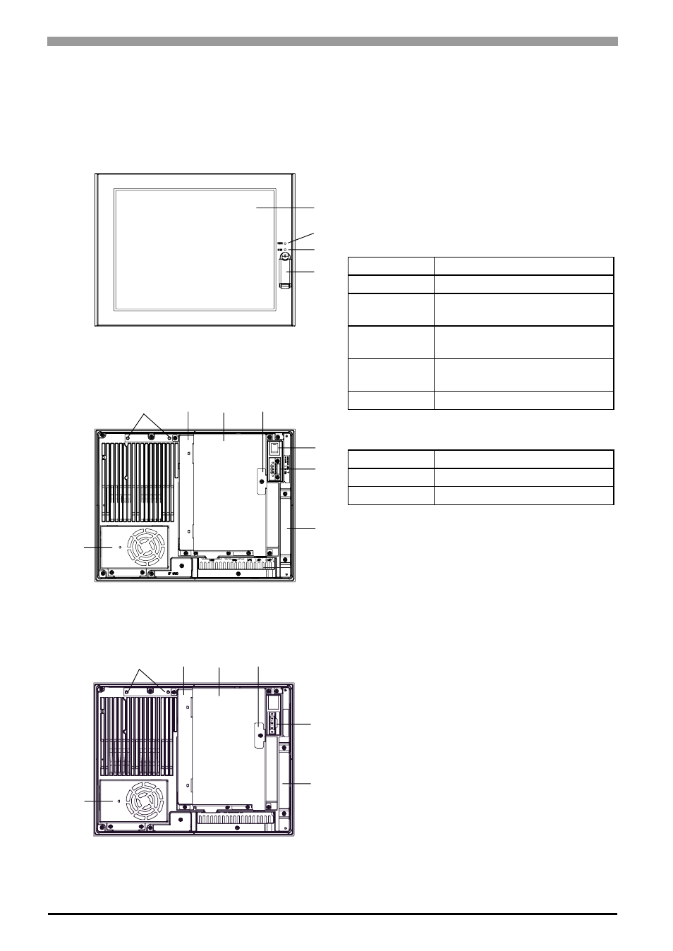
The following images are of a PS-3650A/PS-3651A unit.
A: Display
B: Touch Panel
C: Power LED / RAS Status lamp (POWER)
This status LED indicates the power current and
operation status. The following table shows the
display colors and corresponding status.
D: HDD/IDE Access lamp (DISK)
E: Front Cover
Inside, there is a Hardware Reset Switch (RESET)
and a USB Interface 1 port (corresponding to USB
Ver.1.1).
F: Power switch
AC type only (PS3650A-T41/PS3651A-T41)
G: Power supply connector
For connection, put a power plug (included) into the
power cable.
H: Mask Cover
I:
RS-232C/485 conversion unit hook holes
J:
Expansion Board Base
K: Expansion Board Cover
L: Expansion Board Support
M: Fan Cover
N: Memory Slot Cover
O: IDE Cover
A,B
D
C
E
I
J
K
L
F
G
H
M
I
G
H
M
Front
(Common in PS-3650A / PS-3651A)
Rear
(PS3650A-T41)
Rear
(PS3650A-T41-24V)
J
K
L
LED
PS-A Status
Green (lit)
Normal operation (power is ON).
Green
(blinking)
System is NOT running (Soft
OFF state).
Orange (lit)
System monitor error / Touch
panel SELF TEST error.
Orange/ Red
(blinking)
Backlight error.
Off
Power is OFF.
LED
PS-A Status
Green (lit)
Access to HDD or IDE.
Off
No access to HDD or IDE.