Figure 3-27: lan connector, Table 3-21: lan2_usb1 connector pinouts – IEI Integration KINO-DH810 User Manual
Page 51
KINO-DH810
P a g e 39
CN Typ e :
RJ-45 , USB 3.0 and USB 2.0 ports
CN Lo c a tio n :
See Figure 3-25
CN P in o u ts :
See Figure 3-27, Table 3-21 and Table 3-22
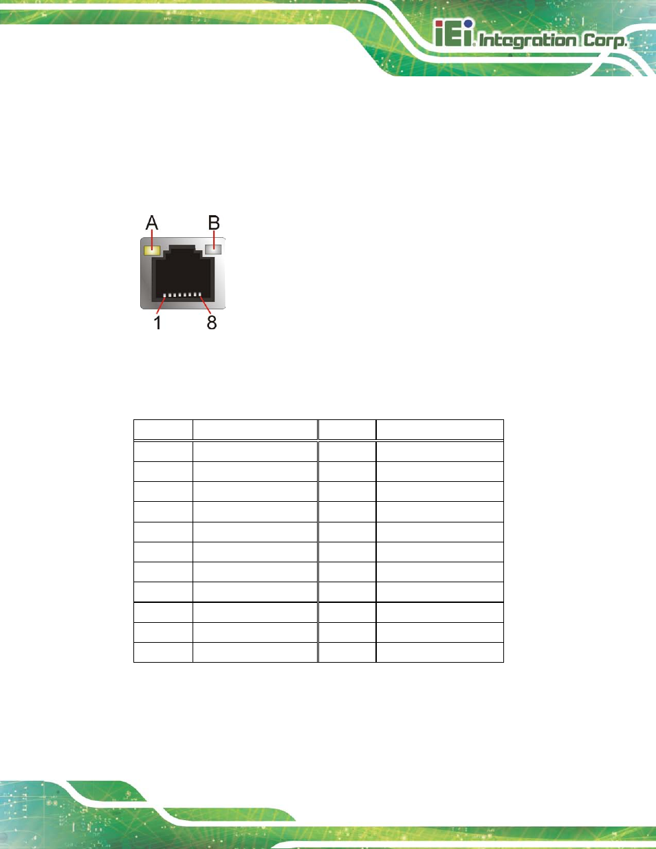
The LAN connector connects to a local network.
Figure 3-27: LAN Connector
The USB 2.0 ports are for attaching USB 2.0 peripheral devices to the system. The
pinouts of LAN2 and USB 2.0 connectors are shown below.
PIN NO.
DESCRIPTION
PIN NO.
DESCRIPTION
P1
+1.5V_LAN2
P2
LAN2_MDIP0
P3
LAN2_MDIN0
P4
LAN2_MDIP1
P5
LAN2_MDIN1
P6
LAN2_MDIP2
P7
LAN2_MDN2
P8
LAN2_MDIP3
P9
LAN2_MDIN3
P10
GND
P11
LAN2_LINK100
P12
LAN2_LINK1000
P13
LAN2_ACT-1
P14
+V3.3A_LAN2
U1
+USB_PWR1
U2
USB20_C_N10
U3
USB20_C_P10
U4
GND
U5
+USB_PWR1
U6
USB20_C_N11
U7
USB20_C_P11
U8
GND
Table 3-21: LAN2_USB1 Connector Pinouts
The USB 3.0 ports are for attaching USB 3.0 peripheral devices to the system. To be able
to use the USB 3.0 ports, please make sure the USB 3.0 driver is installed. The pinouts of
LAN1 and USB 3.0 connectors are shown below.