Ethernet / ip diagnostic leds – Fairbanks FB2255 Series Instrument PC2255 PC Software Utility Program User Manual
Page 45
Section 6: Fieldbus/Bluetooth
01/13
45
51297 Rev. 1
5.2.5.
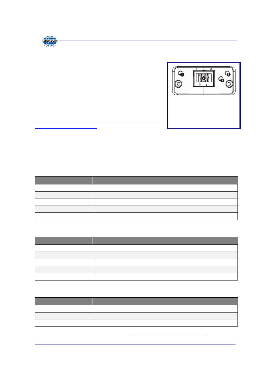
ETHERNET / IP DIAGNOSTIC LEDS
The Ethernet/IP module uses Dynamic Addressing.
– Dynamic Host Configuration Protocol
(DHCP) is used for address requests.
– The data is transmitted continuously from this
module.
– The IP address may be made static by
downloading the IP Configuration Tool
Software from the following site:
http://www.hms.se/support/support.asp?PID=368&Product
Type=Anybus-CompactCom
.
•
Using this download, it is possible to change the IP, Sub Net and Gateway
addresses of an Ethernet/IP Module.
•
To change an address, double click on the IP address field and enter the
changes.
Shown below is the Network Status LED Chart
STATE
DESCRIPTION
Off
Not online / No power
Green
Online, one or more connections established.
Flashing
Online, no connections established
Red
Duplicate IP address, FATAL error
Flashing Red
One or more connections timed out
Shown below is the Module Status LED Chart
STATE
DESCRIPTION
Off
No power
Green
Controlled by a scanner in Run state
Flashing Green
Not configures, or Scanner in idle state
Red
Major fault (EXCEPTION-state, FATAL error, etc.)
Flashing Red
Recoverable fault(s)
Shown below is the Link / Activity LED Chart
STATE
DESCRIPTION
Off
No link, no activity
Green
Link established
Flickering Green
Activity
For more information and EDS files, see
http://www.hms.se/default.shtml
.
1. Network Status LED
2. Module Status LED
3. Link/Activity
4. Ethernet Interface (RJ-45)
(Standard Cat 5 Cable)