Analyzing non-parallel forces, Torque wheel – PASCO ME-9502 Statics System User Manual
Page 39
®
M o d e l N o . M E - 9 5 0 2
E x p . 6 : T o r q u e — N o n - P a r a l l e l F o r c e s
0 1 2 - 1 2 8 7 6 B
35
4.
Perform the calculations to determine the torque,
1
, provided by the Spring Scale, and the percent difference
between
1
and
2
. [The percent difference is the difference of the two torques divided by the average of the
two torques.]
•
To provide a consistent mathematical definition of torque,
1
and
2
must be determined according to the same
formula.
5.
Apply the generalized definition of torque (
= F d sin ) to the calculation of
2
in step 2 previously. [Hint:
What is the angle between the force, F
2
, and the lever arm, d
2
?] Does the calculated value using the general-
ized definition change the results?
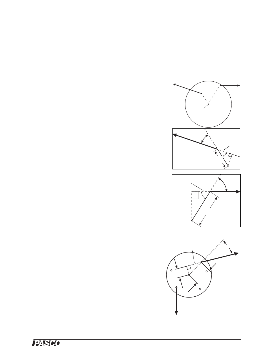
Analyzing Non-Parallel Forces
Imagine two non-parallel forces acting on an object at different distances
from its pivot point. The figure shows a diagram for a calculation of
torque provided by two non-parallel forces. The force F
1
produces a
torque
1
about the point O with a magnitude of F
1
d
1
sin
1
. The force F
2
produces a torque
2
about the point O with a magnitude of F
2
d
2
sin
2
.
However, it would be misleading to simply add the two torques together
to determine the total torque because
1
and
2
cause rotation about point
O in opposite directions. When adding two or more torques, add together
the magnitudes of all the torques that tend to cause clockwise rotation,
then add together the magnitudes of all the torques that tend to cause
counterclockwise rotation. For the system to be balanced, the sum of the
clockwise torques must equal the sum of the counterclockwise torques.
Remember that the perpendicular distance, d
, from the pivot point to the
force is equal to d sin
and that the angle is measured between the lever
arm, d, and the line of force.
Torque Wheel
A Torque Wheel provides an easy method for creating an equilibrium
among several non parallel forces. Figure 6.5 shows a force F applied at
an angle
to the line from the center of the Torque Wheel to the point of
application of the force. The torque can be calculated as
= F d sin .
However, as shown, d sin
is just the perpendicular distance, d
,
between the center of the Torque Wheel and the line of force, when that
line is extended far enough.
Imagine a Torque Wheel with two non-parallel forces. The angle
between the force F
1
and the lever arm d
1
is
. The perpendicular dis-
tance d
1
from the pivot point O to the line of force is d
1
sin
. There-
fore, the torque
produced by F
1
is F
1
d
1
The radial scale on the Torque Wheel label allows you to measure the
perpendicular distance from the pivot point to the line of force. Each
concentric circle on the label is 2 mm larger in radius. Each Torque
Indicator Arm is transparent and has a centerline that shows the line
of force.
F
1
F
2
O
F
1
O
O
F
2
d
2
d
1
d
d
d
1
d
2
Line of force
Line of
force
Pivot
point
Figure 6.4: Non-Parallel Forces
Figure 6.5: Using the Torque Wheel
O
d
1
d
1
F
1
Line of
force