Exp. 4: torque-parallel forces, Theory, Setup – PASCO ME-9502 Statics System User Manual
Page 25: Exp. 4: torque—parallel forces
®
M o d e l N o . M E - 9 5 0 2
E x p . 4 : T o r q u e — P a r a l l e l F o r c e s
0 1 2 - 1 2 8 7 6 B
21
Exp. 4: Torque—Parallel Forces
Equipment Needed
Theory
In experiment 2, you found resultants and equilibriants
for concurrent forces—forces that act upon the same
point. In the real world, forces are often not concurrent.
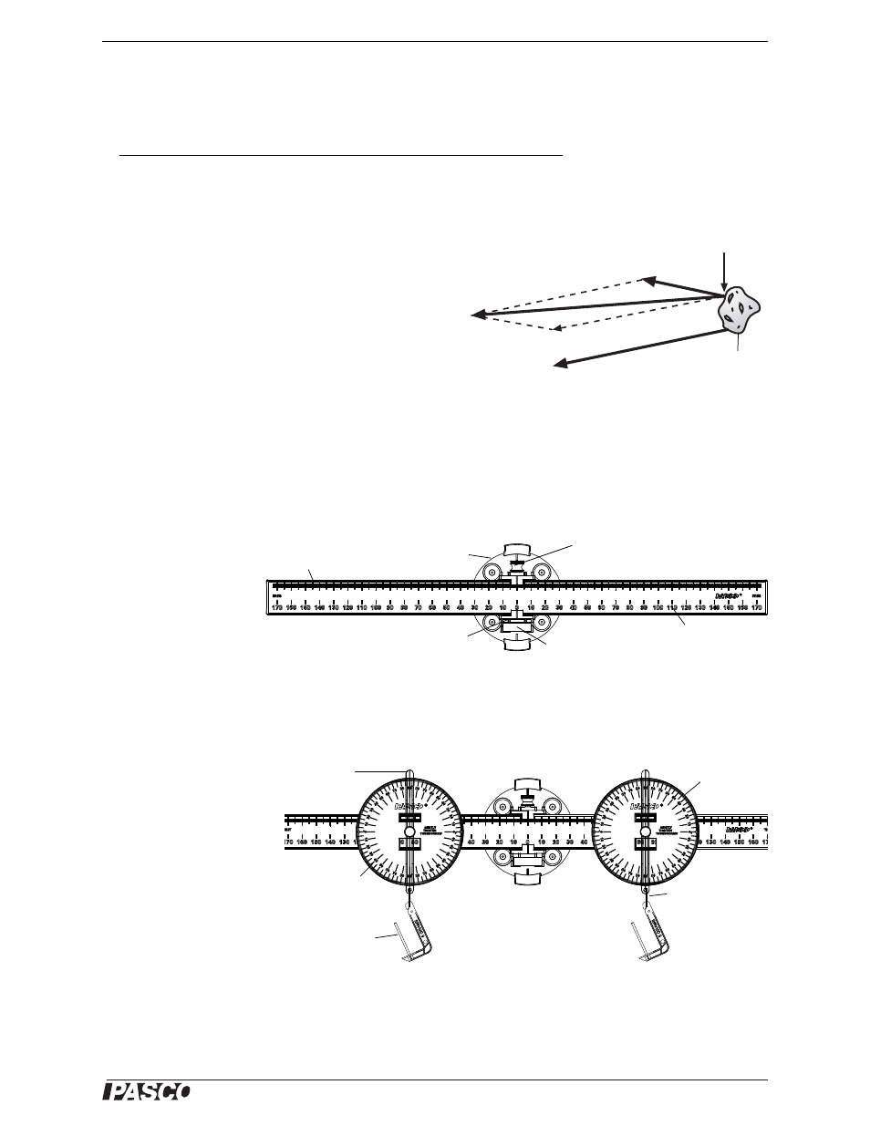
They act upon different points on an object. In the fig-
ure, for example, two forces are pulling on different
points of an object. Two questions can be asked:
1.
In which direction will the object be accelerated?
2.
Will the object rotate?
If the two forces were both applied at point A, the resultant would be the force vector shown, F
R
. In fact, F
R
points
in the direction in which the object will be accelerated. (This idea will be investigated further in later experiments,)
What about question 2? Will the object rotate? In this experiment you will begin to investigate the types of forces
that cause rotation in physical bodies. In doing so, you will encounter a new concept—torque.
Setup
Mount the Balance
Arm near the center of
the Statics Board.
Level the Beam
Loosen the thumbscrew and adjust the beam so that the zero mark on the beam is aligned with the indicator marks
on the pivot. When the beam is level, the bubble in the bubble level will be midway between the two lines on the
level.
Add the Protractors
First, find the mass of two
of the protractors and
record the masses. (Note
that you can use the Spring
Scale to measure the mass.)
•
Protractor 1 =
__________
•
Protractor 2 =
__________
Loosen the thumbscrews on the two protractors and slide one onto each end of the beam. Tie a mass hanger to the
thread on the angle indicator of each protractor.
Item
Item
Statics Board
Balance Arm and Protractors
Mass and Hanger Set
Thread
A
F
R
Figure 4.1: Non-concurrent forces
Object
F
1
F
1
Figure 4.2: Balance Arm
Base
Thumbscrew
Bubble level
Beam
Pivot
Scale
Figure 4.3: Setup
Angle
Indicator
Protractor 2
M
1
M
2
Protractor 1
Thread
Mass
hanger