Balance arm assembly – PASCO ME-9502 Statics System User Manual
Page 12
S t a t i c s S y s t e m
C o m p o n e n t s P a c k a g e ( M E - 9 5 0 5 )
®
8
012-12876B
(Imagine that the Force Wheel disk is transparent so that you can see the String Tie.) Hold the Force Wheel as
shown and push the clear plastic tabs inward with your forefingers until the String Tie pops out of the Force
Wheel.
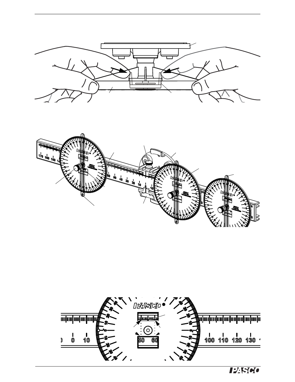
Balance Arm Assembly
The Balance Arm Assembly consists of a Beam, a Pivot, and three Protractors that can be mounted on the beam.
Each protractor has a transparent Angle Indicator. The pivot has a bubble level for leveling the beam.
Adjust the beam by loosening the thumbscrew on the top of the pivot and sliding the beam one way or the other.
Move the protractors by loosening the thumbscrew at the center of the protractor and sliding the protractor along
the beam. Note that not all experiments need three protractors.
Reading the Scale
Read the position of the protractor relative to the midpoint through the two rectangular windows on the protractor.
The bottom window shows the position to the nearest centimeter, and the top window shows the position to the
millimeter. The top window has a small indicator line on its bottom edge. The bottom window in the example
shows the position as between 50 mm and 60 mm and the top window shows it at 55 mm.
String Tie
Base
Force Wheel
Remove String Tie
Beam
Pivot
base
Bubble
level
Protractor
Tie a
thread to
the hole.
Angle Indicator
Thumbscrew
Thumbscrew
Washer
Balance Arm Assembly
Indicator
line
This tick
mark is at
50 mm.
This tick
mark is at
60 mm.
Note: The Angle Indicator is
not shown in this example.
Reading the Scale