General maintenance – Controlled Products Systems Group 222X383 User Manual
Page 60
Installation and Maintenance Manual
52
D0119, Rev. F
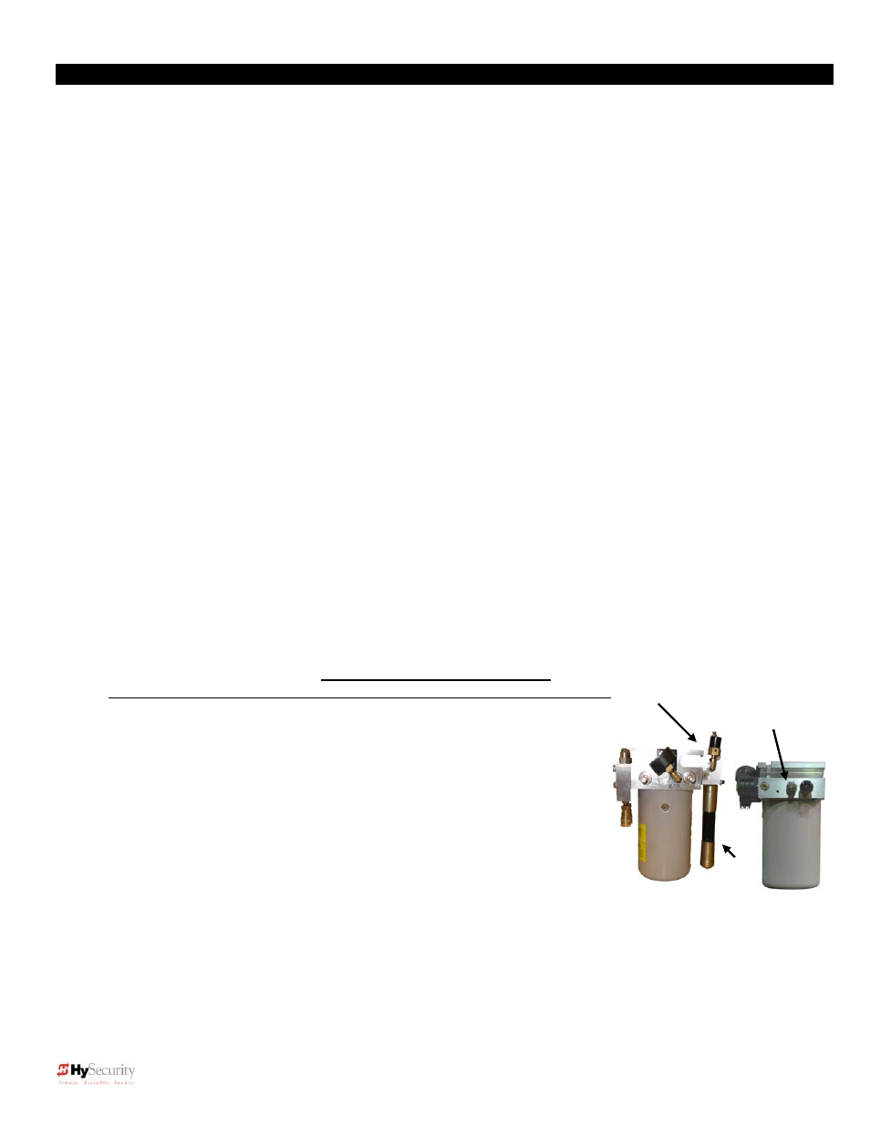
Pressure Relief Valve
Left
: SlideDriver 40, 80, 200
Behind black switch
Right
: Other SlideDrivers
General Maintenance
Hydraulic System
Fluid Level:
Under normal conditions, hydraulic systems do not consume oil. Before adding any oil, check the
system thoroughly for leaks. Remove the bright metal plug in the tank, fill to plug level, then replace plug. We
recommend our Uniflow hydraulic fluid; part # MX000970, which is sold in one-gallon containers by a
HySecurity distributor. Never use brake fluid. It will severely damage the entire hydraulic system. Use of
any oil other than Uniflow fluid may void the operator warranty.
Look for leaks:
Occasionally there may be slight seeping at the fittings due to shifting in transit or after some
usage. Tightening of the fittings will usually correct the problem. If the leaking persists, replace "O" rings,
fittings or hoses, if required. No further leaks should occur.
Oil Change:
A hydraulic system does not foul its oil, unlike a gas engine, so oil changes do not need to be
frequent. Oil breakdown caused by heat is the main concern. If the unit is subjected to high use, especially in a
warm climate, change the oil more frequently. In general, we recommend draining the reservoir and replacing
the oil at five-year intervals.
To change the hydraulic oil, remove the reservoir from the pump unit, completely empty it, wipe the reservoir
clean, and clean the derby screen before re-assembling. Refill with new Uniflow hydraulic fluid (available from
your distributor). To avoid overfilling, fill only through removable plug near the top of the tank. Slowly pour the oil
into the tank until the oil is within one inch of the filler port. Replace the plug and wipe up any spilled oil. If any
oil is allowed to remain, it will dry to a very sticky and messy consistency.
Cold Weather:
1. Check that your reservoir is filled with our Uniflow high performance fluid.
2. Ice can partly or totally jam gate operation. Check function by operating the gate manually.
Electrical Controls
-
Before servicing, turn off power disconnect switch
No routine maintenance is needed for the electrical system or controls. If the environment is very sandy or
dusty, or has many insects, be certain to seal all holes in the electrical enclosure. Blow the dust out of the
electric panel with compressed air. A qualified technician may troubleshoot with the aid of the troubleshooting
guide in this appendix. If it is necessary to call a distributor for assistance, be sure to have your model and
serial number ready. Other helpful information would include the name of the job, approximate date of
installation, and the service record of the operator, especially any work that has been done recently.
Pressure Relief Valve Adjustment:
WARNING! - The gate will move!
Only experienced hydraulic gate technicians should perform these tasks!
1. Locate the Pressure Relief Valve on the pump assembly, (right).
2. Loosen the 9/16” locknut on the Relief Valve.
3. Put a wrench on the adjusting screw, (5/32” Hex or ½” flat head).
4. With the gate attached and the wheels clamped, run the operator with
the OPEN, CLOSE and STOP keys on the operator keypad. As the
motor/pump runs, turn the adjusting screw clockwise, raising the
pressure. (Until the valve is properly set, the motor will run for 2-3
seconds, stop and generate a “SAFE” or “Entr” code.)
5. Reset by pressing the keypad RESET key, repeat step 4 until:
a. The gate starts and runs consistently w/o displaying “SAFE” or
“Entr”; OR
b. Maximum pressure for the operator is reached. Do not exceed maximum pressure ratings below
6. If the gate system requires more than rated maximum pressure contact HySecurity 800-321-9947.
7. While holding the adjuster screw with the wrench, tighten the 9/16” locknut on the valve.
MODEL
MAXIMUM RELIEF SETTING
SlideDriver 10, 40
1000 PSI
SlideDriver 30F, 40F, 80
1300 PSI
SlideDriver 200
2000 PSI
AWOG
There is limited value in using the relief valve
as an entrapment protection device. Photo
Eyes or gate edges are the best methods to
protect pedestrians and maintain reserve
power to reliably drive the gate.