Installation – Controlled Products Systems Group 222X383 User Manual
Page 19
Installation and Maintenance Manual
11
D0119, Rev. F
Installation
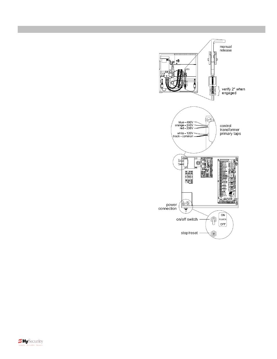
6. Clamp the Drive Wheels to the Drive Rail
When the wheels are fully clamped on the drive rail, the red
spring should be compressed to 2” in height. If adjustment
is necessary, turn the nut at the bottom of the threaded rod
assembly. Slightly less compression is okay for lighter
gates. See Use of Manual Release on page 54
7. Electrical Power Connection
This operator is intended for permanent installation, so all
electrical conduits must be properly connected to the control
box. The entry for the primary power is a ½ - ¾” knockout
on the left side of our control box next to the on-off switch.
When this operator was manufactured, it was built to run on
a specific voltage and phase for line power. Make sure you
have compared the line voltage and phase available with the
nameplate on this machine. They must match! Be certain
that the wire size of the branch circuit that will supply the
operator vs. the distance of the run from the main panel is
large enough to avoid excess voltage drop. At a minimum, a
20 amp circuit (protected with a 20 Amp Inverse Time
Breaker) should be provided. Also be sure the operator is
electrically well grounded per NEC Article 250 and local
codes. See pages 61 and 62 for correct wire sizes and
detailed electrical wiring information.
8. Primary Tap of Control Transformer
(not on battery operators)
Check to make sure that the primary tap on the control
transformer matches the line voltage you have connected to
the operator. Measure the line voltage carefully to
distinguish between 208V and 230V branch circuits. A label
on top of the transformer identifies the various voltage taps.
9. Electrical Power for Two Part 333 type operators
The primary AC power must be routed to the controller
enclosure with the pump, but there must also be conduits between
the gate operator and the controller enclosure.
Note: AC power is not needed in the gate operator, unless there is an optional heater. A minimum of two
separate conduits must be provided, 2” for the hydraulic hoses and ¾” for the electrical interconnections.
Unless there are accessories in the gate operator, the only electrical interconnection between the two
enclosures will be three wires between the two terminal strips for the limit switches. Join the hydraulic
hoses by plugging the quick coupling together according to the hand of the gate. See the on page 59.