Mechanical and hydraulic adjustments – Controlled Products Systems Group 222X383 User Manual
Page 21
Installation and Maintenance Manual
13
D0119, Rev. F
Mechanical and Hydraulic Adjustments
1. Drive Wheel Spring Tension
When the drive wheels are fully clamped on the rail, the red spring should be compressed to 2” in height. Turn
the nut at the bottom of the threaded rod assembly to adjust. Slightly less compression is okay for lighter gates.
(See Figure on page 11)
2. Drive Rail
With wheels unclamped and manually moving the gate, verify that the drive rail does not vary more than 1” up
and down, or ¼” in and out throughout the entire horizontal travel of the gate. Re-alignment is simple if the rail is
mounted with U bolts. To adjust in and out, loosen the U bolts and add or remove shim stock. To adjust up or
down, loosen the U bolts and simply tap the rail with a hammer until the correct height is reached. Adjusting the
rail in or out requires inserting shims between the rail and the gate where necessary.
3. Brake Valves
SlideDriver 40 & 30F (222 E & EX 1.7) models only
If your operator is equipped with brake valves, their proper adjustment
is important for smooth operation of the gate. In order for the brake
valves to have time to function, the limit ramp must trigger the limit
switch at least six inches before the point at when you want the gate to
stop. Adjustment of the brake valves, one for each direction of travel,
will determine how quickly the gate actually stops. If adjustment is
needed, loosen the 9/16” lock nut on the top of the brake valve and turn
the adjustment stem, in about ¼ turn increments, with an Allen wrench.
The adjustment works opposite of typical, a counter-clockwise
adjustment will stop the gate more rapidly. If the adjustment is set too
loose, the limit ramps will bang into the drive wheels. If the adjustment
is set too tight, the system pressure will increase, the gate speed may
decrease and the gate will jerk to a stop. Set the brake valves to
achieve a controlled smooth stop, with the limit ramp 1.5” to 3” from the
wheels, then retighten the locking nut to hold the setting.
4. Pressure Relief Valve
The operating pressure limit is factory preset to a level that will
operate most gates well. A gate may require pressure relief
valve adjustment on install. To provide maximum entrapment
protection, do not set the pressure limit higher than necessary
for good operation (see procedure and maximum settings on
page 52). This valve, which governs the maximum system
hydraulic pressure, is located on the backside of the pump,
above the AWOG on SlideDriver 40 and on the same manifold
but facing the operator chassis on other operator models.
Reduce the relief valve setting to the lowest pressure that will
reliably operate the gate. A lower
setting reduces the operator’s
maximum force.
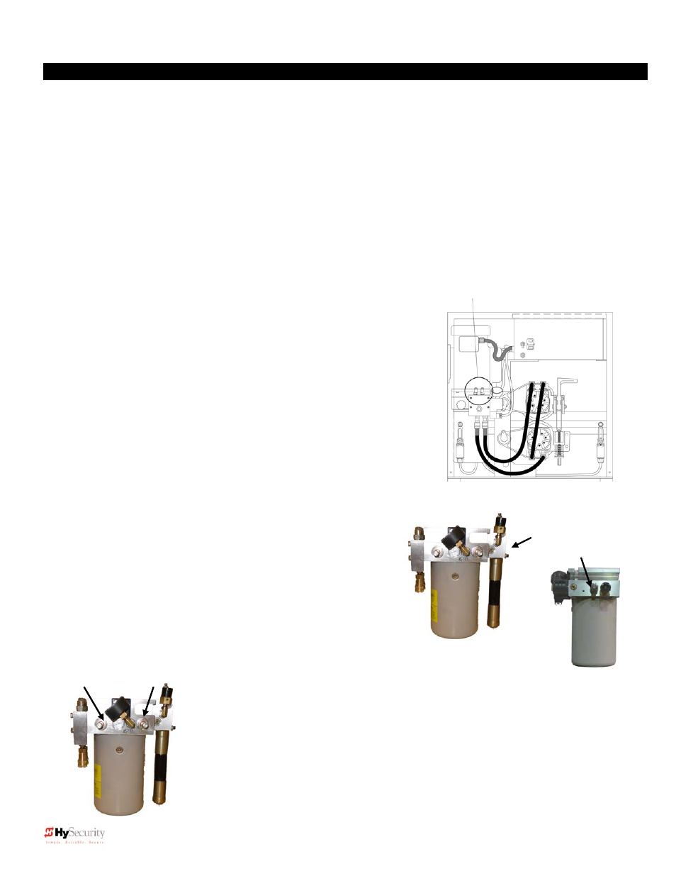
5. Open and Unloader Valves
These two valves are solenoid operated. The Open valve is below the motor near
the front of the pump and energizes in order to direct the hydraulic flow to open the
gate. The Unloader valve, which is near the back of the pump energizes at the
beginning of a cycle to allow no load motor starts and at the end of each cycle to
aid in decelerating the gate. No adjustment of these valves is possible or
necessary. Valves are wrapped with black plastic valve coils.
Optional brake valves CCW = quicker stop
Left valve controls open
Right valve controls close
“Right Hand” Hose connections shown
Pressure Relief Valve
Left
: SlideDriver 40, 80, 200
Behind black switch
Right
: All other models
Open Valve Unloader
Valve