Controlled Products Systems Group 222X383 User Manual
Page 49
Installation and Maintenance Manual
41
D0119, Rev. F
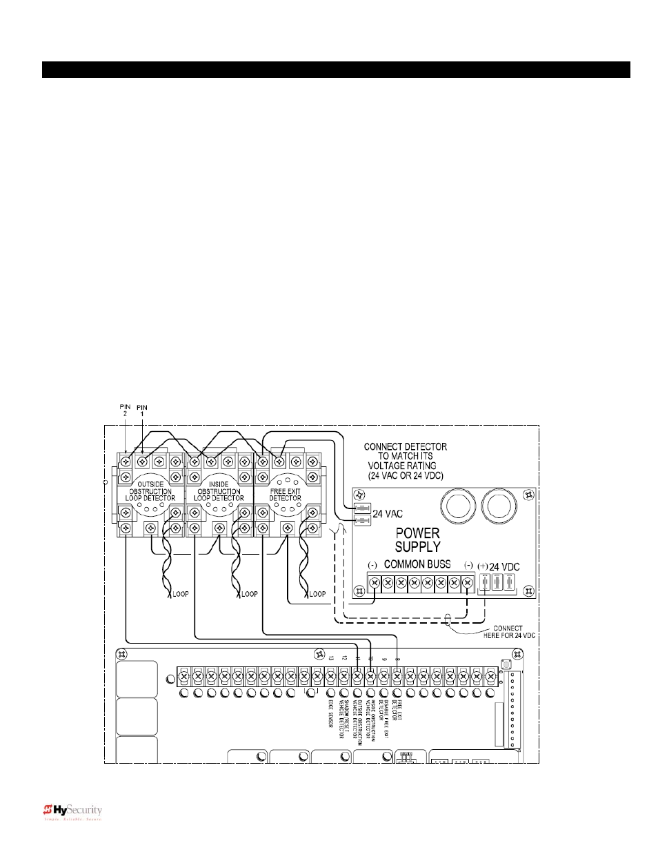
Standard 11 Pin Box Type Vehicle Detector Installation
1. If standard 11 pin vehicle detectors are to be used, install the sockets into the control box (if there is
room) or in a separate external housing. The diagram below is for connection reference only. Other
items may already be installed in the physical area where the sockets are shown.
2.
Both 24 Volts AC or DC are available, so either detector voltage may be used (24 VAC is not available if
the operator is a battery type). 24 VAC is available at the spade terminals on the lower left corner of our
power supply (marked ACC). 24 VDC is available from the Common Buss and the +24 V spade
terminals next to the Common Buss.
3.
Connect 24 Volt power to the detector. Polarity does not matter if the detector is a 24 AC model. If a DC
detector is used, pin #1 is (+) on a DC detector and pin #2 is ( - ).
4.
Connect the output pin #6 to the Common Buss on the power supply and the output pin #5 to one of the
four detector inputs (depending upon the detector function required) on the Smart Touch Controller
terminal strip.
5.
If multiple detectors are used, run the power wires and common wire from socket to socket rather than
running each to the same location separately. The only wires that are separate are the output wire to
the Smart Touch Controller and the loop input wires.
6. Always keep the loop wires well twisted at all places beyond the area of the loop. The lead in portion
sealed in a saw cut does not need to be twisted so long as the wires are encapsulated in loop sealant
and cannot move.