Sliding gate entrapment protection – Controlled Products Systems Group 222X383 User Manual
Page 12
Installation and Maintenance Manual
4
D0119, Rev. F
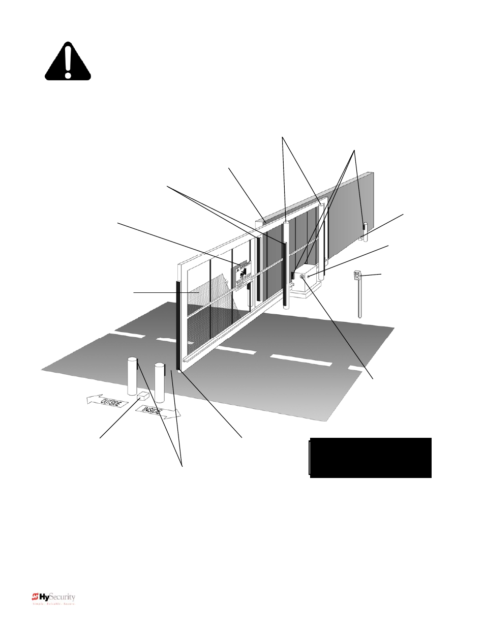
Sliding Gate
Entrapment Protection
Guard posts
Keep this gap as
small as possible
Gate edge
sensors
Warning signs must
be on both sides
2” safety mesh
prevents reach-
through: height not
less than 48 inches
Physical travel
stop, both ends
Photo Eyes for
both directions
each side of gate
Gate edge sensor,
on leading edge
and trailing edge
Audio alarm
Physical travel
stop, both ends
Note:
All wheels must be
covered. (Wheels and
covers not shown for clarity)
This schematic view is not meant to recommend the only way to set up your configuration, but
to point out the various elements of a proper automatic vehicular gate installation. The gate
operator itself is only one component in the total system. Always install a separate
pedestrian gate.
Stop and reset
button
Access controls
at least six feet
away from gate
and operator
Photo Eyes for
both directions