Logic elements, And gate, Logic elements -41 – Clear-Com Logic-Maestro User Manual
Page 55: And gate -41
Clear-Com Communication Systems
Eclipse Logic Maestro Instruction Manual
1 - 4 1
LOGIC ELEMENTS
Logic elements are used to perform logical operations on the outputs
of control sequence elements and pass the result to the input of other
control sequence elements. This allows complex sequences of
actions depending on various conditions to be built up and
programmed into the matrix system. Right click on the logic elements
in the Logic Elements pane to display an options menu. This menu
allows the user to display a truth table for the logic element or copy the
logic element to the design window.
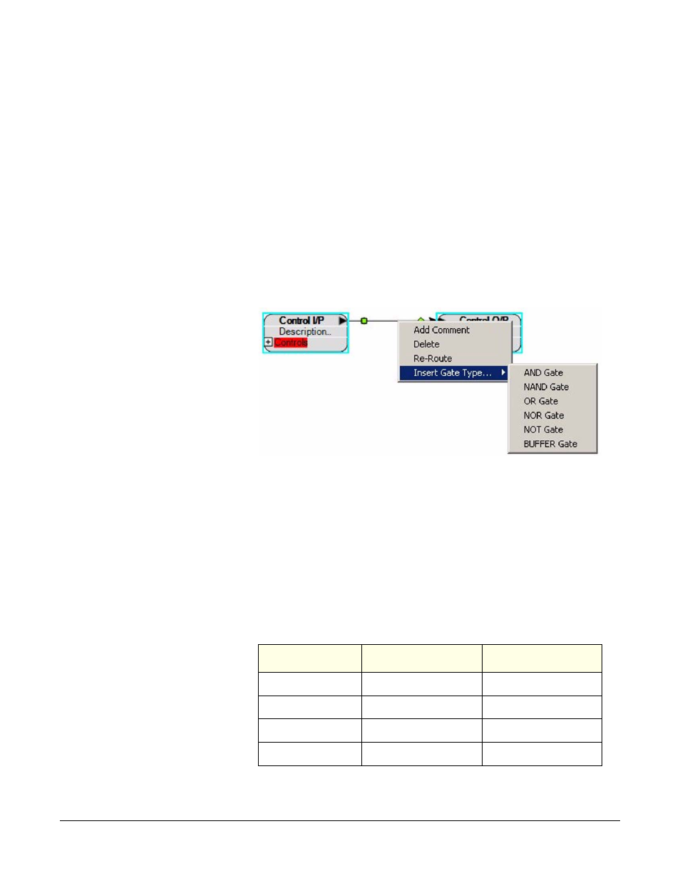
Logic elements can be inserted existing connections by right-clicking
on the connection to display the options menu and selecting ‘Insert
Gate Type’. A list of logic elements will be displayed for insertion into
the connection.
Figure 1-76: Inserting a Logic Element into a Connection
The logic elements available are described below.
AND Gate
Combines two or more inputs to generate a single output. The default
is two inputs but by right clicking on the AND gate to display the
options menu additional inputs can be added. Unused inputs will
default to the TRUE state. The output is only true if all the inputs are
true. The AND gate adds a 25ms processing delay.
Table 1-1: Truth Table for AND Logic Element
Input A
Input B
Output
False
False
False
False
True
False
True
False
False
True
True
True