Control and display elements, Operating status, Control and display elements of the positioner – Burkert Type 8696 User Manual
Page 25
25
Controlanddisplayelements
7.
CONTROL AND DISPLAY ELEMENTS
The following chapter describes the operating statuses as well as the control and display elements of the
positioner.
For further information on the operation of the positioner, refer to chapter “11. Start-up”.
7.1.
Operating status
AUTOMATIC (AUTO)
Normal controller mode is implemented and monitored in AUTOMATIC operating state.
→ LED1 flashes green.
MANUAL (MANU)
In MANUAL operating state the valve can be opened and closed manually via the keys.
→ LED1 flashes red / green alternately.
The DIP switch 4 can be used to switch between the two operating states AUTOMATIC and MANUAL.
7.2.
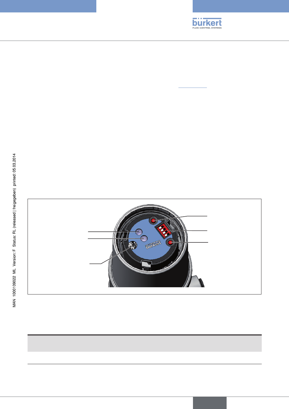
Control and display elements of the positioner
DIP Switches
Key 2
Key 1
LED 1
LED 2
Communications
interface
Figure 9:
Description of the control elements
The positioner features two keys, a 4-pole DIP switch and 2 2-coloured LEDs as a display element.
→
Screw off the transparent cap of the positioner to operate the keys and DIP switches.
NOTE!
Damage or malfunction due to penetration of dirt and humidity!
• To observe protection class IP65 / IP67, screw the transparent cap in all the way.
→
Close the device (assembly tool: 674078
6)
).
6)
The assembly tool (674078) is available from your Bürkert sales office.
english
Type 8696