Brooks, Mf series – Brooks Instrument Mfi Series User Manual
Page 55
4-17
Brooks
®
Mf Series
Section 4 Maintenance &
Troubleshooting
Installation and Operation Manual
X-TMF-Mfi-Mfx-MFC-eng
Part Number: 541B074AAG
August, 2009
If adding two 0.005” thick large diameter flow clearance spacers for
controllers with 0.007” and greater orifices or removing both 0.002”
thick small diameter flow clearance spacers for orifices less than 0.007”
does not provide adequate flow, the orifice size should be checked. See
Section 4-6, Orifice Sizing. If the size is correct inspect the orifice for
clogging and clean as required following Section 4-2D, Cleaning. After
cleaning, start the spacing procedure over using the initial spacer
configuration.
7. After achieving adequate flow, apply 11 Volts to valves with orifices
<.032" or 18 Volts to valves with orifices
≥ .032". Measure the flow.
This voltage should provide less than 2% leak rate with elastomeric
valve seats and less than 3% leak rate with metal valve seats. The leak
rates given here are percentages of full scale for the gas on which the
controller was calibrated. For all controllers calibrated for gases other
than Nitrogen, the measured leak rate must be converted using the
procedure in Section 4-6, Orifice Sizing where Q
Nitrogen
is the measured
leak rate and Q
gas
is to be determined.
Once Q
gas
has been calculated it must meet the following:
Q
gas
≤ 0.02 x Full Scale Flow of calibrated gas (elastomeric seat)
If the measured leak rate is greater than the respective allowable
values, for all orifice sizes, add a 0.005” large diameter air gap spacer.
Refer to Figure 4-3b for spacer placement. Continue to add a 0.005”
thick large diameter air gap spacer until the leak rate is within the
required specification for the valve seat in use. If adding two 0.005”
large diameter air gap spacers does not yield the correct leak rate, the
valve seat and orifice should be inspected for damage and replaced as
necessary.
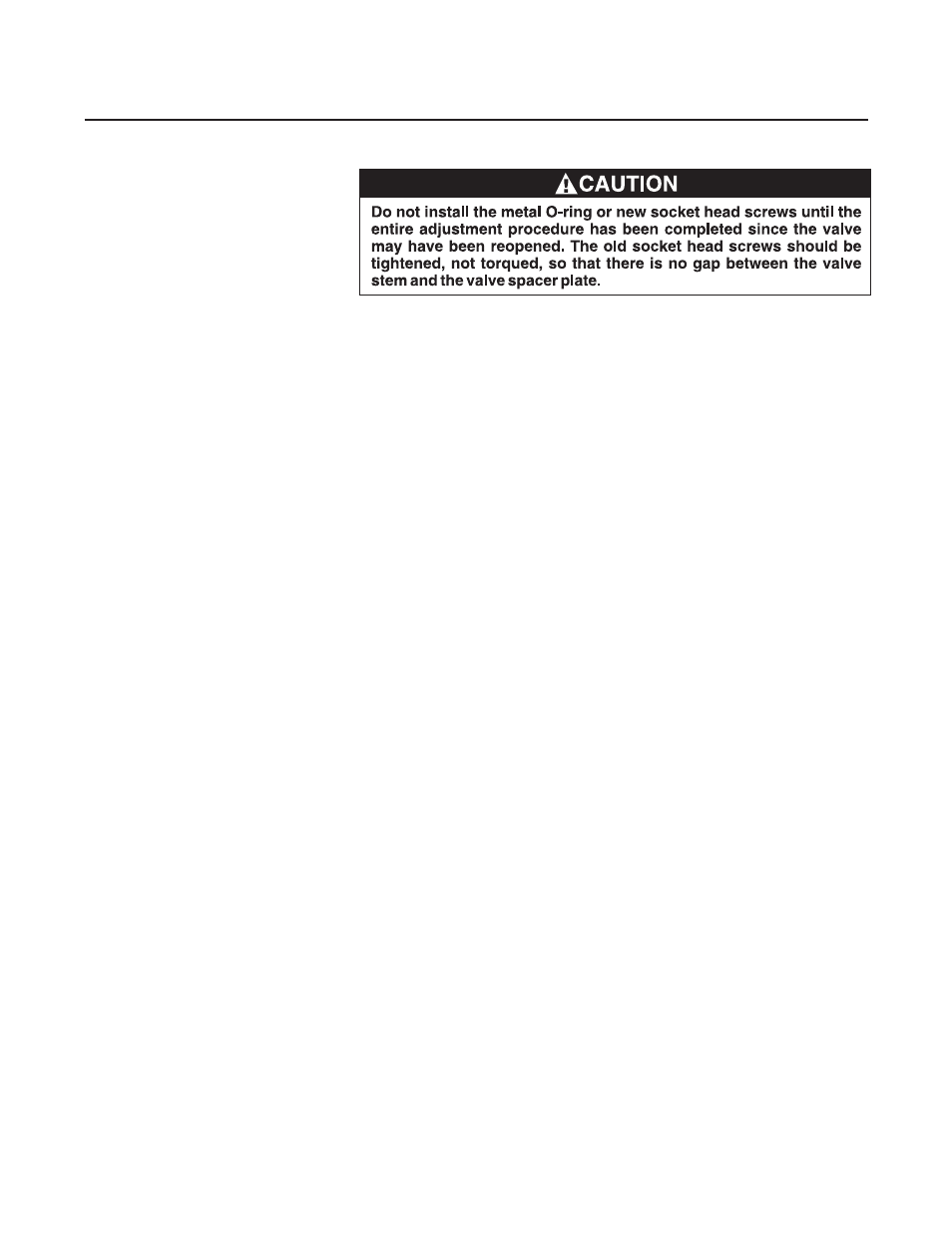
8. At this point the valve is properly adjusted. Replace the elastomeric
O-ring with the new metal one and reassemble using the new socket
head cap screws following Assembly, Section 4-4.
Note: Be sure to lubricate the screws to insure proper clamping force
and prevent seizing when torqued.