Brooks, Mf series – Brooks Instrument Mfi Series User Manual
Page 12
1-4
Brooks
®
Mf Series
Section 1 Introduction
Installation and Operation Manual
X-TMF-Mfi-Mfx-MFC-eng
Part Number: 541B074AAG
August, 2009
1-5 Electrical Specifications
Setpoint Command Requirements (Controllers)
4-20 mA (75 ohms input resistance). The 4-20mA setpoint signal must be
supplied from the customers side(sourcing type).
The input load for this signal is 75 ohms.
For 0 to 5 Vdc (220 K ohms input resistance)
Output Signals
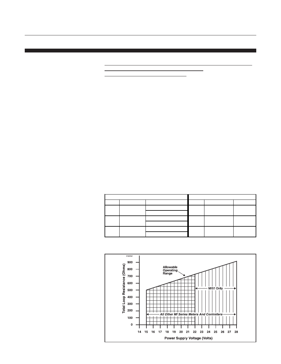
0/4-20 mA, loop resistance is power supply dependent, refer to Figure 1-2,
or 0 to 5 Vdc into 2000 ohms, or greater load. Maximum ripple 3 mV.
Power Requirements
Refer to Table 1-2.
Electrical Connections
Wire hookup is through a Pg11 water tight cable gland suitable for cable
diameters of .20 to .39 inches or 1/2" FNPT conduit fitting.
Wiring termination's are pluggable moving vise clamp with screw type
terminations. Refer to Figure 1-3 for termination points and Table 1-3 for
terminal identification and functions.
Typical Electrical Configuration
Figure 1-4 illustrates typical electrical hookup to Brooks 0151i Power
Supply/Set Point Controller/Readout.
Figure 1-2 Maximum Allowable Output Loop Resistance
Table 1-2 Power Requirements
Mass Flow Controllers
Mass Flow Meters
Model
Voltage
Current
Model
Voltage
Current
Mf50 15 to 28 Vdc
240 mA @ 15 Vdc
Mf60
15 to 28 Vdc
90 mA
370 mA @ 28 Vdc
Mf51**15 to 28 Vdc
309 mA @ 22 Vdc
Mf61
15 to 28 Vdc
90 mA
370 mA @ 28 Vdc
Mf53 15 to 28 Vdc
240 mA @ 15 Vdc
Mf63
15 to 28 Vdc
90 mA
370 mA @ 28 Vdc
** Note minimum voltage for Mf51 is 22 Vdc